

I'd like to thank these guys too! It's admirable all the work and support they've given to the community.
Aw got it now. I was lost for the schematic I just downloaded and had I had it before I'd be able to had answered myself. As those resistors are just for the LED I know how to size them.
Thanks! I will update accordingly, and now that I found the schematic (dumb me) I will follow your tips.
Anyway to know how dirty my power is, without an oscilloscope? It's only 7 bucks for the components on the CLC, but on the other hand as you say, I don't want to build it if I don't need it. I'm intending to get a meanwell PSU, would that mean by itself that the power coming from it is clean enough?
I will also omit the switch board. I was interested in the LED, but I'll jsut use the main board one through a JST connector as suggested by JPS!
Your posts have been very helpful for many people who are wondering how hard it is to build this. Probably the hardest part is the BOM. I forget that sometimes because I generally have all the parts on hand except for maybe an electrolytic cap or special silver mica cap. So I forget how hard it is to find everything. Thank you for putting together a shopping cart BOM to share.
You are right, $7 is not much and if you don’t mind adding it, it can’t hurt. It also prevent noise from the switch mode DC-DC from going back and contaminating your mains.
Hi X,
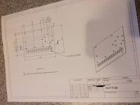
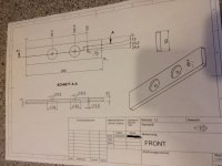
I´ll publish all the plan and if demand I´ll offer the custom heatsink in GB.
But today, I´m still waiting for the mechanical part.
JP
I´ll publish all the plan and if demand I´ll offer the custom heatsink in GB.
But today, I´m still waiting for the mechanical part.
JP
Guys,
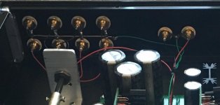
Check out the noise floor on this PSU, it uses a TI TPS7Axxx 4uV rms LDO regulator before the cap multiplier. The ripple in the “grass” of the FFT is much reduced.
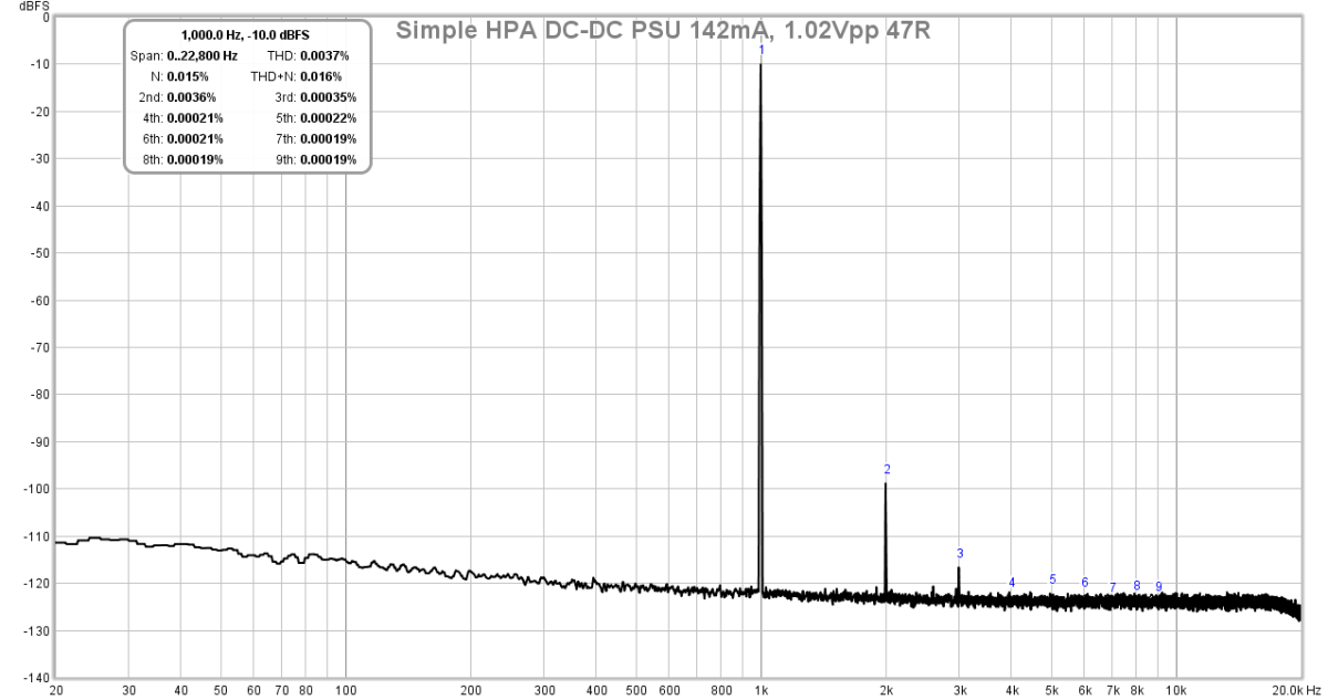
This is for the TimS simple DC coupled HPA. But I was thinking perhaps a such a mod might be useful for those interested in ultimate low noise PSU. It’s likea battery.
Check out the noise floor on this PSU, it uses a TI TPS7Axxx 4uV rms LDO regulator before the cap multiplier. The ripple in the “grass” of the FFT is much reduced.
This is for the TimS simple DC coupled HPA. But I was thinking perhaps a such a mod might be useful for those interested in ultimate low noise PSU. It’s likea battery.
Those connectors are headers and header pins. For the main board I used 10-pin headers and cut them as needed to get the 3-pin and 6-pin headers. The important thing with these parts is that you get 2.54mm pin spacing. I used these:
Mouser #710-61301011821
And for the header pins I used these. Make sure you get right angle pins if you don't get these.
Mouser #538-22-28-8034
One more tip. BUY EXTRA! When I cut my first 10-pin header one of the pieces I needed went flying into the abyss that is my garage. Still haven't found it. I had to wait for my next Mouser order before I could keep building.
Okay, one more tip. Buy extra of all the cheap stuff or if you get a good price break by buying in quantity. You never know when that extra resistor will come in handy or work for the next project. And there will be a next project. 😉
Last edited:
Then you can splash out a bit more and get good audio grade caps for C123 and C133, like JPS64 (original BOM) or X suggested in post #634.I just want to spend the money where it scientifically makes sense.
Or these:
AKSA's Lender Preamp with 40Vpp Ouput GB
From what I gathered from you guys' last two posts I put together this new BOM Mouser Electronics I'm trying to keep this one clean and public for the next beginner because really, this hasn't been fun. lol
Jwjarch pointed out that your values for C125 and C135 need to be .1uF, not 4.7uF. It looks like you fixed that in the BOM, but there are two more caps you can remove from the cart - C127,C137 (Nichicon 0.1uF electrolytics) – they are replaced by C1027, C1037 (Vishay 0.1uF Film), which is already in your cart.
+1One more tip. BUY EXTRA! ....
there will be a next project. 😉
Another noob question. On implementing multiple inputs - is it better to switch both the + and - (ground) of the input channels? To do this one need a 4 pole switch. In the example here of Vunce's amp, the 4 input channels all share a common ground and only the + side of the signal is switched to the amp input. Is this common practice? Can this open up possibilities for ground loop issues? I read (Alan Wright's Cook Book) that one should separate the channels as early as possible, but no need to do this here if the channels share common ground on the pcb anyway, which I am not sure of.
Attachments
Looking at the schematics and the PCB for the MB, C137 and C1037 are either or, correct?
Why then on the BOM, C137 is 0µ1/100V/MKC1860 and C1037 is 1µ0/250V/MKS4 ?
I thought they should be the same value, just optional types? However C1037 is 10 times more capacitive than C137. I believe this is correct, I just wanted to learn the reason why they have different values. I assume the C1037 is a better option according to TwoCents, I just wanted to understand why and why the values are different.
Thanks Twocents and jwjarch. I have updated the BOM and also finished the BOM for the DB. I will soon post them for future reference, together with stuff I bought elsewhere. I have deleted the C127,C137 and opted for C1027 and C1037.
I had an error I believe where C125/135 was an electrolytic. I changed that for a Film Capacitors 0.1uF 305V. Is this a good choice? Edit: I believe this is the direct replacement for the original BOM:VIshay Film Capacitors 0.1uF 100volts 5%... Or should I just get these: Dayton
I will also look into one of the recommended audio caps for position C122/132
Last edited:
Last question: what is the connector X114 for? It is the only 3pin connector I can tell and I can see nowhere to connect those to..
GASCo, X114 are output pins for a headphone jack. Only used if you are building this as a dedicated headphone amp or plan to swap DB's when you want to switch between preamp and headphone amp.
Yes, looking at the schematic you will see that both C137 and C1037 are optional bypass caps for C136, but why they differ 10 times in value I do not know either. Waiting for some reply as I also want to learn. I guess it is part of cap rolling?Looking at the schematics and the PCB for the MB, C137 and C1037 are either or, correct?
Why then on the BOM, C137 is 0µ1/100V/MKC1860 and C1037 is 1µ0/250V/MKS4 ?
I thought they should be the same value, just optional types? However C1037 is 10 times more capacitive than C137. I believe this is correct, I just wanted to learn the reason why they have different values. I assume the C1037 is a better option according to TwoCents, I just wanted to understand why and why the values are different.
C127 = C137: equipped in my version and is KP1860 0µ1/100V/5% axial.
C1027 = C1037: not equipped in my version = capacitor width 8mm and pitch 15mm (WIMA 1µ0/250V/MKS4).
C126 = C136: SILMIC 220µ/50V (using 1U enclosure).
PS.: raw sheet of aluminium arrives tomorrow (enough for 3 heatsink pair); mechanical milling and drilling this weekend!
JP
C1027 = C1037: not equipped in my version = capacitor width 8mm and pitch 15mm (WIMA 1µ0/250V/MKS4).
C126 = C136: SILMIC 220µ/50V (using 1U enclosure).
PS.: raw sheet of aluminium arrives tomorrow (enough for 3 heatsink pair); mechanical milling and drilling this weekend!
JP
@GASCo
Headphone Amplifier Version:
Using X114 instead of X112/X113 for JACK headphone wiring: X112/X113 not equipped.
Preamplifier Version:
Using X112/X113 RCA, X114 not equipped.
JP
Headphone Amplifier Version:
Using X114 instead of X112/X113 for JACK headphone wiring: X112/X113 not equipped.
Preamplifier Version:
Using X112/X113 RCA, X114 not equipped.
JP
Ok, with good reason nobody replied to this noob question in post #649. I did some homework (scrutinized the pcbs) and see that the ground is common throughout. X even commented about that in the GB thread:Another noob question.
I agree and have high regard for people like JP who did these layouts!Again, thank you to Aksa for the design and JPS64 for the layout! This is truly a superb "professional" layout - very similar to what you would see in a final end-product. You will notice extensive use of copper pours/ground planes, separation of signal and power ground planes, nice connectors to allow the boards to be placed in the users' case with the most flexibility as to where input/output jacks go, etc.
Thanks JP, Twocents and jwjarch.
Questions on the TH DBs:
1- X said at some point that for R15 a multi turn trimpot could be used to adjust bias. My understanding is that this is just to equalize bias between channels, correct? In this sense, can I have one DB stuffed with a regular R15=47R5 and in the other channel only have a multiturn 50K trimpot?
2- R10 to adjust gain, to my understanding according also to X, has to be a metal film resistor. In this case what values should I buy to have a good range of gain? I will for now use this preamp to power a Pass ACA (15db) but plan to build a F4 or MoFo in the not too distant future. R10 is described as 10K but I have no idea of how sensitive the gain is to changes in this resistor.
So far I bought the following items, this might be useful for another beginner sourcing parts:
DBTH (1 channel): Mouser Electronics
MB: Mouser Electronics
35W 24v power supply: Genuine Mean Well MW 24V 35W RS-35-24 AC/DC Switching Power Supply 6959687379173 | eBay
DC-DC booster: DC-DC 10-32v to 35V-60V 120w Boost booster module electric motorcycle charging 545247976072 | eBay
IEC jack (my PSU will be inside the chassis): 250V 10A IEC320 C14 Mount Male Plug 3 Pin Panel Power Inlet Socket W Fuse Switch 6942096049027 | eBay
RCA jacks: https://www.ebay.com/itm/10-RCA-Fem...e=STRK:MEBIDX:IT&_trksid=p2060353.m2749.l2649
Chassis: https://www.ebay.com/itm/2205-Full-...e=STRK:MEBIDX:IT&_trksid=p2060353.m2749.l2649
Output capacitors (Based on this guy I prefered to get these because of shipping costs elsewhere to buy other capacitors): https://www.ebay.com/itm/2pcs-Audio...e=STRK:MEBIDX:IT&_trksid=p2060353.m2749.l2649
DB heatsinks: https://www.ebay.com/itm/5pcs-21x15...e=STRK:MEBIDX:IT&_trksid=p2060353.m2749.l2649
MB heatsink: https://www.ebay.com/itm/Silver-Alu...e=STRK:MEBIDX:IT&_trksid=p2060353.m2749.l2649
Mica Insulators: https://www.ebay.com/itm/TO-220-Mic...e=STRK:MEBIDX:IT&_trksid=p2060353.m2749.l2649
Thermal paste: https://www.ebay.com/itm/New-1g-Sil...e=STRK:MEBIDX:IT&_trksid=p2060353.m2749.l2649
And of course the PCBs (Still have to get these): https://www.etsy.com/listing/612861271/aksa-lender-se-class-a-preamp?ref=shop_home_active_6
Last edited:
GASCo, it looks about right, but check for the following changes on the DB TH BOM. It is a bit difficult for me since you have not included the pcb Part numbers in the Mouser BOM.
R10 – Keep it at 10k (carbon film recommended), see Post #608.
R11 – Increase this to lower the gain, see Post #602.
R11 = 1k for MoFo, F4
R11 = 2k2 for ACA, M2
Good, I see that you have made the following corrections to the BOM for the MB:
R141 – 10k, not 220R
V141 – 1N400X rectifier diode, not zener or breakdown
Great, looks like you are good to go!
- Home
- Source & Line
- Analog Line Level
- AKSA's Lender Preamp with 40Vpp Output