But how connect heatsink to backplate? The case construction not allowed it, that is the problem.
no no no...
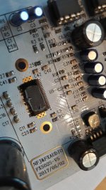
forget in the moment the purple heatsink. use some silikon pads and give it under the TPA3250 chip (you see on the pic 1 the lot of holes...then you mount the pcb into the buttom case = this is your new heat sink !

Some heatsink should be connected here
View attachment 676202
but too smal distance to bottom part of the case.
Сonnect directly to bottom part of the case impossible due to the design of the case - bottom part moving when you insert the board
is not correct = because the srews are bigger , so fill up the room between the 2 screws with silicon pads and then it have to fit to the buttom plate of the amp case...
sorry now i am out.....cycling
nice friday...

Are you all thinking about this type of pad?
100x100x1mm Blue Heatsink Cooling Thermal Conductive Silicone Pad Cooler Mat New | eBay
I see them in 0.5mm and 1.0mm thickness, how much room is under the PCB?
100x100x1mm Blue Heatsink Cooling Thermal Conductive Silicone Pad Cooler Mat New | eBay
I see them in 0.5mm and 1.0mm thickness, how much room is under the PCB?
The purple heatsink is functional, because through the conductive screws it cools the pcb, but there is no free air, so that is limited, more limited than the outer enclosures function as heatsink.
@noasds
yes...the screws connecting the buttom pcb trough the material of the screws to the upper purple heatsink
Are you all thinking about this type of pad?
100x100x1mm Blue Heatsink Cooling Thermal Conductive Silicone Pad Cooler Mat New | eBay
I see them in 0.5mm and 1.0mm thickness, how much room is under the PCB?
no idea....measure it....
...sunny afternoon...
Hi
in the morning I did the final check between original amp1 and the mod amp2 with just changed op amp BB2134. i used the same psu = original.
the original amp is still a fine good amp. the original opamp inside are not original brand-see post before....
Sound:
the BB2134 ais able to focus and keep the interprets in the "required" place, they are not moving during playing music. the BB2134 is able to give you 1m more left an right room without streching everything in strange order. voices and instruments are more "real" with a nice deepness.
both amps are silent no hiss.
chris
inside FX502Spro - V5
Hi
i opened completle the amp and I made some pics. i am not really sure if this chip is the real TP3250, The with label is very weak.
i measure the big caps = rubycon 1800µ/35V and i found a datasheet were i see 3 different sizes for this yxg series...so it looks ok for me.
i opend the first amp = amp 1. its a blue board with whit pcb at the volume knob. so its a version 3. no optical diverence in layout. the coils have different plastic cover and the caps at this side looks different....
i decided to change here tha opamp. so in the future the amp1 is with LM49720........and amp 2 is still with BB2134
lets burn in and check the sound LM49720 vs BB2134
cu chris
Hi
i opened completle the amp and I made some pics. i am not really sure if this chip is the real TP3250, The with label is very weak.
i measure the big caps = rubycon 1800µ/35V and i found a datasheet were i see 3 different sizes for this yxg series...so it looks ok for me.
i opend the first amp = amp 1. its a blue board with whit pcb at the volume knob. so its a version 3. no optical diverence in layout. the coils have different plastic cover and the caps at this side looks different....
i decided to change here tha opamp. so in the future the amp1 is with LM49720
........and amp 2 is still with BB2134lets burn in and check the sound LM49720 vs BB2134
cu chris
Attachments
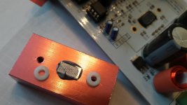

...mod .....cooling situation...
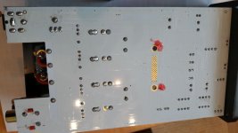
i pick up the idea from post before und mod the lower part of the pcb where the tpa3250 is mounted. if you measure the distance between the lower line of the pcb to the buttom alu case plate you measure about 5,1mm.
i found a ceramic resistor MPR5N 0,1 Ohm (link below) in my box and cut the pins and give on both side thermal paste and stick it between the screws of the chip and slide the pcb back to the alu case. i checked the position and evereything is fine.
so in the future I sould measure on the buttom plate a hot spot under the chip.
resistor MPR5N - Google Search
chris
Last edited:
Looks like improvements of v5 are in the white color of the board only
we will see...
step by step...actually the amp 1 V3 blue is running with the lm49720....first impression is very good....after fair "burn in phase" i will compare to the amp2 (BB2134)....if there is a difference ...i will change the opamps vice versa...
watch out if you fix the resistor ...measure carefully...5,1mm ..if you hold the pcb in one hand and fix the ceramic resistor then slide with the other hand the alu buttom case....dont crack the pcb...
have a nice weekend.
Well parts differ, I don't see the lm2596hvs for example, the part 3250 doesn't need but got earlier, the part 3255 board needs but didn't get
??
please explain...mybe i got too much sun..
Is this a newer version? What does the pcb look like on the ones people have ordered? This one says REV 3 and has white pcb for vol VR board.
FX AUDIO FX502S PRO HIFI 2.0 Audio Digital High Power Amplifier Home Mini Professional Amp TPA3250 NE5532 *2 70W *2 on Aliexpress.com | Alibaba Group
This seller has different photos from other sellers.

@irribeo
the 12V regulator is on the blue pcb on board....look at the pic previos post
I got a pair of LME49720 chips today. How do I tell the direction they go in? There is the printing on the top of the chip and the half-circle notch out of the left side. Do I put them in with the writing going the same direction as the stock chips? There is not a mark on the first leg as some pictures show (and others do not).
10% safety factor for capacitor, Oh~Ye - thks fr confirm, now i have peace of mind supply FX502spro with meanwell configured 31V.
You have a point on heat problem, my thoughts of using 31V beyond 24V:
~ TPA3250 Power output depends on voltage -- was hoping 31V provides more for any transient music peak.
~ 24V from LM317~1.5A if undergood dissipation
Rough estimate: This 24V supplies NE5332 Op-Amp (datasheet 16mA) , to LM2596HVS gives 12V for TPA3250 Logic/Gate control (datasheet 40mA), to AMS1117 to provide 3.3V for 8bit MCU ST S003F3P6 (datasheet 100mA) ~ total max approx 0.16A
LDO LM317 ~ 7V drop gives 1.2W heat.
What else did i missed?
2 items unsure:
~ International Rectifer IRF9530N -- what function on FX amp?
~ Does FX TPA3250 back-stage driven by whatever voltage from DC Supply voltage (OR being internally regulated by LM317 - i highly doubt, but not sure what jigglebones is implying)?
some mentioned hvs over and over again, I think earlier versions had the hvs, which didn't make sense, while on 3255 board it does make sense but the standard version was used.
you won't measure lower capacitance on rubycons after very heavy use for years, meter must be off or...i measure at the big caps ( 2 caps are parellel) with my LCR meter and i got 3400 µF so its ok for 2x1800µ F with +- 20% tolerance
- Home
- Amplifiers
- Class D
- TPA3250 somebody is listening?