thanks for confirming FX's Opamp are indeed supplied with +/- 12V...
Who confirmed that? 😕
Thanks doctormord asking again, the conclusion based on putting below bits-pieces together:
reading at Op-amp socket pin 8 +Vcc=24V, pin 4 -Vcc=0V.Jigglebones, another matter to clarify as i consider your LME49720NA swap on FX amp, as i measure the Op-amp socketed Vcc pin8, reads 24v as supplied by on-board LM2596HVS...
The FX Audio FX502SPRO uses a LM317 regulator to step-down the input voltage to 24V single rail DC (single-supply DC) to the two unbalanced to balanced converter OpAmps. If sums up the +- supply voltages of an OpAmp is equal to or more than 24V DC, it is safe to use in the amplifier.
...
So doesnt pin 8 +Vcc=24V, pin 4 -Vcc=0V equates to +- 12V?...I read a document in DIY solid amp board years ago, it said that most OpAmp are much good sound in listening test between +-10V to +-12V DC. I thinks the FX development team will follow this rule to set the voltage for OpAmp because this company is an OEM/ODM for solid and D-AMP....
10% safety factor for capacitor, Oh~Ye - thks fr confirm, now i have peace of mind supply FX502spro with meanwell configured 31V.
You have a point on heat problem, my thoughts of using 31V beyond 24V:
~ TPA3250 Power output depends on voltage -- was hoping 31V provides more for any transient music peak.
~ 24V from LM317~1.5A if undergood dissipation
Rough estimate: This 24V supplies NE5332 Op-Amp (datasheet 16mA) , to LM2596HVS gives 12V for TPA3250 Logic/Gate control (datasheet 40mA), to AMS1117 to provide 3.3V for 8bit MCU ST S003F3P6 (datasheet 100mA) ~ total max approx 0.16A
LDO LM317 ~ 7V drop gives 1.2W heat.
What else did i missed?
2 items unsure:
~ International Rectifer IRF9530N -- what function on FX amp?
~ Does FX TPA3250 back-stage driven by whatever voltage from DC Supply voltage (OR being internally regulated by LM317 - i highly doubt, but not sure what jigglebones is implying)?
...I do NOT recommend operating the FX on anything other than its normal 24V-- even on lower voltage the components will get hotter as the regulatory circuit probably tries to step it up to 24V...
Last edited:
....
LDO LM317 ~ 7V drop gives 1.2W heat.
]jigglebones[/URL] is implying)?
Hi Jigglebones
Actually i can read that you are intensive checking the FXPRO.
the heat of 1,2 Watt is not less. Did you check the small heatsink (left bottom corner) on that regulator? i guess on the very last pic of the open case pic i found
Buy Products Online from China Wholesalers at Aliexpress.com
thx
chris
Last edited:
Hi Jigglebones
Actually i can read that you are intensive checking the FXPRO.
the heat of 1,2 Watt is not less. Did you check the small heatsink (left bottom conrern) on that regulator? i guess on the very last pic of the open case pic i found
Buy Products Online from China Wholesalers at Aliexpress.com
thx
chris
I'm not trying to imply anything, only sharing my observations.
To clarify, my electrical knowledge starts and ends with V=IR. I barely passed physics class when they made us learn Kirchoff rules etc. I'm more of a chemistry person 🙂
I only chose the LME49720 based on reading other stuff online, and my ears told me that it was the right choice. Yes I am aware the spec on the chip is max 17V but it seems to work OK. Would the higher-voltage spec version, the LME49860 be better? Some say its the same chip anyway. And I don't remember exactly but the NE5532 is not exactly rated for 24V either.
I am only assuming the way the regulator circuit works is to regulate the voltage to 24V because that is what it was configured to (I am sure there is some way to adjust it, but don't know what it is). Yes, I am using a variable linear PS, and I tried different voltages from 20-30V. In my opinion 24V sounds the best, and I did notice the case was getting hotter on any voltage other than 24V (higher OR lower!). TBH it would probably be better to bypass the regulation completely, but I do not have any interest in messing with things I don't understand.
I try to learn little bit where I can, but my interest is in listening to the amplifier not soldering things. My other interest is also not spending a lot of money, which is why I am drawn to the DIY/chi-fi side of audio.
Last edited:
Hi
thx for your feedback.
i starting with diy too...so i am a noob but i try to understand - I sort myself to do not getting in a totally caos 😀
i am waiting for mine and its boring.... so ....i made a list of all the eventuelly task i will try. so if anybody has some ideas...feel free..
cu
chris
thx for your feedback.
i starting with diy too...so i am a noob but i try to understand - I sort myself to do not getting in a totally caos 😀
i am waiting for mine and its boring.... so ....i made a list of all the eventuelly task i will try. so if anybody has some ideas...feel free..
cu
chris
Attachments
Last edited:
chermann/chris, that aliexpress order link is not visible by any of us.
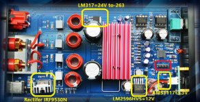
Anyway i took a PCB clip and labelled various power components.
The small heatsink (left bottom corner) you referred is not LM317, but International Rectifer IRF9530N (not idea its function here)
The LM317 is not on any little heatsink (upper & next to TPA3250 heatsink instead), but uses PCB copper as heatsink.
Yep, 1.2W is not less - and total 0.16A from datasheet may not be typical but rather worst case.
So what does everyone think: Does that little PCB copper at LM317 able to dissipate 1.2W?!? LM317 thermal shutdown at 125 degC, but my immediate concern wld be those surrounding caps at 85 degC, and aircoils.
I just did a size compare with 1W/2W resistor (which usually didnt even get any PCB heatsink support) and "guesstimation" if LM317 able to dissipate 1.2W.
On the right, marked Red are 4 connector poles - not sure if what can we use it for - wish to add to your list as well? 😀
Attachments
Last edited:
thanks for reply, in my case, i want to use these amps for pa setups so i need all the power i can get 🙂. tpa3250 would for for little pa setups like portable boom box...Found a 150w one ...
Oh PA amps, now i get it why you put-on a Sure 30V, 300W dc-dc boost converter supply. Dont forget to put-on a heatsink on that TPA3250 3eaudio.
chermann/chris, that aliexpress order link is not visible by any of us.
Anyway i took a PCB clip for labelled the various power components.
That small heatsink (left bottom corner) that you refer is not LM317, but International Rectifer IRF9530N (not idea its function here)
The LM317 is not on any little heatsink (upper & next to TPA3250 heatsink instead), but uses PCB copper as heatsink.
Yep, 1.2W is not less - and total 0.16A from datasheet may not be typical but rather worst case.
I just did a size compare with 1W/2W resistor (which usually didnt even get has any PCB heatsink support) and "guesstimation" if LM317 able to dissipate 1.2W.
So what does everyone think: Is that little PCB copper at LM317 able to dissipate 1.2W?!? LM317 max-out at 125 degC, but my immediate concern wld be the surrounding caps at 85 degC, and aircoils.
On the right, marked Red are 4 connector poles - not sure if what can we use it for - wish to add to your list as well? 😀
thanks for your explanation ...perfect....😎...yes i will add this to my list.😉
..update...
please can you attach the foto as a file
i want to save your pic...but its too small
please can you attach the foto as a file
i want to save your pic...but its too small
Attachments
Last edited:
Without seeing the circuit and the traces on the board I would speculate and can imagine two reasons for placing an IRF9530N power mosfet near the power supply socket:Anyway i took a PCB clip and labelled various power components. The small heatsink (left bottom corner) you referred is not LM317, but International Rectifer IRF9530N (not idea its function here)
- protection against false poling of the external power supply
- protection against other false operating conditions (overdrive, heat,...) derived from the TPA chip protection circuit
Of course switching power mosfet could be used for remote switch-on/off of the whole amp but that hardly would be this case.
please can you attach the foto as a file
i want to save your pic...but its too small
Hey dude, here you go.
Attachments
So doesnt pin 8 +Vcc=24V, pin 4 -Vcc=0V equates to +- 12V?
No, as it is relative to GND. +-12V needs +12V on VCC (8) and -12V on VSS (4), relative to GND. The opamps here are running with dc-bias and coupling caps as the board does not feature a symmetrical power-supply.
Thank doctormod for making the point, i redo the measurements and ...
With +12V on VCC (8) & -12V on VSS (4), shorting both L-R RCA input:
If reference to VSS, All input pins are now 12V : ie. 1IN- (2), 1IN+ (3), 2IN- (6), 2IN+ (5). If reference to VCC, All input pins are now -12V: ie. 1IN- (2), 1IN+ (3), 2IN- (6), 2IN+ (5)
Is this above is what you mean by the opamps here are running with dc-bias and coupling caps? Final question: does it mean we can safely use opamp such as LM4562 (supply max +-17V) on FX502spro amp?
chermann/chris, that aliexpress order link is not visible by any of us.
Anyway i took a PCB clip and labelled various power components.
The small heatsink (left bottom corner) you referred is not LM317, but International Rectifer IRF9530N (not idea its function here)
The LM317 is not on any little heatsink (upper & next to TPA3250 heatsink instead), but uses PCB copper as heatsink.
Yep, 1.2W is not less - and total 0.16A from datasheet may not be typical but rather worst case.
So what does everyone think: Does that little PCB copper at LM317 able to dissipate 1.2W?!? LM317 thermal shutdown at 125 degC, but my immediate concern wld be those surrounding caps at 85 degC, and aircoils.
I just did a size compare with 1W/2W resistor (which usually didnt even get any PCB heatsink support) and "guesstimation" if LM317 able to dissipate 1.2W....
Thk MBA on the IRF9530N power mosfet, with your inputs i wld consider it not connected to any regulator on the PCB.
Further on: I redo a "finger heat/temp sensing" - with 32V DC supply, L-R RCA input shorted, the LM317 is not hot to touch at all , though there is some heat (guesstimate 50-60 DegC?). similarly for all remaining regulator as well. Aircoils also have some heat.
Last edited:
Thk MBA on
Further on: I redo a "finger heat/temp sensing" - with 32V DC supply, L-R RCA input shorted, the LM317 is not hot to touch at all , though there is some heat (guesstimate 50-60 DegC?). similarly for all remaining regulator as well. Aircoils also have some heat.
Hi Forestgump
the finger test methode is in my case always strange with my fingers because if i touch I feel really hot - the measurement tool shows about 48 degree C.
if I study some videos from Dave EEblog 😀 i learnt that the regulators should not have more then about 50°C for longer life (noise...?) . please use a infrared tool.
coil temperature? why? = no load ? => attention not ok for Class D !
cu
chris
Last edited:
Thk MBA on the IRF9530N power mosfet, with your inputs i wld consider it not connected to any regulator on the PCB.
Further on: I redo a "finger heat/temp sensing" - with 32V DC supply, L-R RCA input shorted, the LM317 is not hot to touch at all , though there is some heat (guesstimate 50-60 DegC?). similarly for all remaining regulator as well. Aircoils also have some heat.
sorry i did not read well....my fault
as you wrote in this thread...post #22
running with no load
~ re-adjusted "finger sensing calibration" to 48°C 😀
(dint have infrared tool)
i think when i felt the heat ~ Heatly but not burning hot.
In fact even at DC supply 24V, regulator & Aircoils are mildly warm & then in relationship - attached 2W 6.8ohms resistor to the Spkr output, no warmth on felt on Rs.
Any FX502spro out there, chk out & share findings?
Till then: will adopt "hear only the good news" 😀
Last edited:
... Can it be that the "smoothing stuff" is optimised to a specific output voltage, and works a bit too hard when fed with higher voltages than 24vdc?
- Home
- Amplifiers
- Class D
- TPA3250 somebody is listening?