Huh! Look at that - the current one on the website (v2.1) does use opamps, but the schematic linked in the manual above doesn't. I was really confused for a few min looking at the old schematic... 😀 😀 😀
The TP Placid uses opamps which is why it's probably voltage limited.
I am going to build this project for a very good friend. He is a golden ear audiophile and has designed speakers for some big names. He is now 81 and cannot solder so he asked me to build him a new preamp. His highly modded Dynaco PAS died.
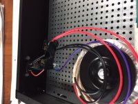
The boards and many of the puzzle pieces are on order. I will build it on a piece of plywood to test everything before building it into a case.
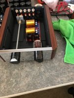
The initial plan is to be completely dual mono. Separate transformers and power supplies for left and right channels.
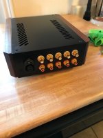
His system is all BNC so I will carry over his I/O jack plate or disassemble and install individual jacks.
The boards and many of the puzzle pieces are on order. I will build it on a piece of plywood to test everything before building it into a case.
The initial plan is to be completely dual mono. Separate transformers and power supplies for left and right channels.
His system is all BNC so I will carry over his I/O jack plate or disassemble and install individual jacks.
How to dial P1 and p2 to 0 ohms
Sorry for this question, but I'm not sure how this goes.
Measure from outer leads?
Doesn't look that too much variance is happening..
Thanks.
Sorry for this question, but I'm not sure how this goes.
Measure from outer leads?
Doesn't look that too much variance is happening..
Thanks.
Sorry for this question, but I'm not sure how this goes.
Measure from outer leads?
Doesn't look that too much variance is happening..
Thanks.
If I remember correctly, I am pretty sure I set mine in the middle of the range....usually they come that way. if unsure, twist one way until it clicks. Then twist the other way until it clicks again, counting each revolution....then turn back 1/2 of that number.
Russellc
If you look at the boards, only 2 of the 3 pins are actually used, so just measure the resistance between those two and set to the desired value.
Sorry for this question, but I'm not sure how this goes.
Measure from outer leads?
Doesn't look that too much variance is happening..
Thanks.
You need to be on the middle leg and one outer legs to read a varying resistance. You can zero it out in either direction so it depends on which way you orient the pot. Easiest thing to do is solder the pot in and then measure across C1 using P1 to zero it out. do the same at C2 using P2.
Last edited:
Isolation washers
Do I need to to install isolation washers in the bolt/nuts between the output mosfets heat sinks and the bigger heatsinks, which would be really extensions of the latter?
Thanks.
Do I need to to install isolation washers in the bolt/nuts between the output mosfets heat sinks and the bigger heatsinks, which would be really extensions of the latter?
Thanks.
Its between the interface between the output mosfet and the heatsink...
The mosfet also has a heatsink...
Thanks
The mosfet also has a heatsink...
Thanks
That't not a heatsink - it's the case and electrically connected to drain.
So yes, you need to insulate the Mosfet front the heatsink using mica and grease, keratherm, or some similar insulator.
These work beautifully - Keratherm Transistor Insulators – diyAudio Store
So yes, you need to insulate the Mosfet front the heatsink using mica and grease, keratherm, or some similar insulator.
These work beautifully - Keratherm Transistor Insulators – diyAudio Store
Its between the interface between the output mosfet and the heatsink...
The mosfet also has a heatsink...
Thanks
I think you mean between the metal tab on the misfit and the heatsink.
The answer is yes if anything will or can accidentally touch the heatsink like the top of the case, etc.
I would isolate the mosfets from the heatsink because there is a big resistor down on the board awfully close.
Which resistor values do I need to change to decrease the gain?
And are Takman Metal Film resitors ok for this build?
And are Takman Metal Film resitors ok for this build?
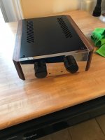
Preamp finished
Finally got around to finishing the chassis and hooking the mechanicals up. I will work on the power supply next and wire everything up. I will cross my fingers and hope all is well. May need help setting bias.
Finally got around to finishing the chassis and hooking the mechanicals up. I will work on the power supply next and wire everything up. I will cross my fingers and hope all is well. May need help setting bias.
Attachments
Antek Transformer to power supply
Would appreciate your help. I gather that I would have to connect both primary red wires to AC positive input and the 2 primary blk wires to AC neutral.
The Purple wire is for what? I assume chassis ground?
And about the secondary wires, 2 are green and two blue... One pair of blue/greens extend longer than the other pair, is this indicative of how to connect them?
How do I connect these to my PS board inputs. Inputs are labeled as S1/S2 pairs. Thanks in advance.
Looking into this further, I gather that one pair of blue/green wires that come out from the transformer further back but together, belong to one winding and the other pair of blue/green that come out at a different position belong to the other winding. So, I should connect the blue wire from one winding to the green wire of the other winding.... And the primary connection as described in my previous post. Is this so? Thanks.
Furthermore, the blue/green connected together from different windings should be center tap, and the other 2 blue green should be 20 v each...
Are you building this for US mains or European mains??
And the answer to your secondary question is “maybe”, what’s your PSU? I’m sorry if I didn’t see that info earlier...
And the answer to your secondary question is “maybe”, what’s your PSU? I’m sorry if I didn’t see that info earlier...
120v mains. Power supply is dual PS from twisted pear audio... Supposedly I have to connect two center outputs together to get +24 and - 24v according to them.
Did this connection to check voltages across primaries (120V) and secondaries.
Fuse WAS a 1 amp fast Blow, It blew immediately. No loads on secondaries...I was checking for voltages, is this what went wrong --i.e., no loads.
I guess 1 amp fuse was sufficient. Thanks guys.
Attached Thumbnails
Fuse WAS a 1 amp fast Blow, It blew immediately. No loads on secondaries...I was checking for voltages, is this what went wrong --i.e., no loads.
I guess 1 amp fuse was sufficient. Thanks guys.
Attached Thumbnails
Attachments
- Home
- Amplifiers
- Pass Labs
- The BA-3 as preamp build guide