Hi
it is from a paper, this idea, I think reinvent the wheel is not needed here, the window does prevent shift down of the carrier when driven hard I did read there. <snip>
Aha Yes, I know now, Well, I think "Russian version" or UCD+ seems to be superipor and much simpler then this.... This is over complicating (just my opinion), probably not that easy to implement in real design.
I thought you were going to try this method I linked from russian forum..., as it seems you did, but I cant follow any more, you implemented many designs, but didnt name them.
So which design is this on the last three images, last post ? Seems not to be from Osted DTU paper, and also not from "russian forum" I linked. And looks like pre filter feedback.
Becasue this was implemented on "russian forum" in real desing, and with real thd measured 0,001% THD, lets continue with this.. seems very simple feedback.
Attachments

Last edited:
You are possible right, but I do learn from it, and this is just what I want to do, afcouse together with your informations, I was also busy with a triangle version, who is open loop, making the triangle as precise as possible and with feedback.
I think about the transitor network just make a amp who has much headroom can make things simple, and use good protections, special current, and dc.
the paper is old, and is not a deign but more a studie what happens with multipole designs, who can be unstable.
These are UCS,s self oscillation versions though, I did see the last did best, and looks like yours special the error amp.
Good idea with the antiparallel transistors, works like a limiter, when overdriving sound get limited and bad I see you using a
series resistor so limiting is less hard, avoid trouble getting unstable?.
Here I did seen a amp, from International Rectifier who use also such kind of error amplifier, youre has more poles.
https://www.google.nl/url?sa=t&rct=...tutorial.pdf&usg=AOvVaw269YxhSpC5SN0_jy-m1PAC
regards
regards
Last edited:
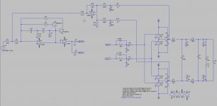
This is a smart one, here I can implement easely a full bridge right? because the feedback lines are present, did you try bessel feedback lines so fase is stable in time?. Only it has heavy feedback, I did get low distortions with local feedback with using good lowpass, maybe a bessel constant fase lowpass is a idea, you now I do not like feedback, it is maybe different in a switching amplifier.
Did not see the comparator double feedback lines for both half of output signals, I do see the error amp is as from IR.
The amp I do work on now has current feedback, I did have such one and did sound very very good, nerver had a better one seen for mine ears, but the hybrid tube mosfet did outperform that one later, so is mine favorite, but learing is always nice ofcourse.
last picture is of present build, a allfet circlotron, busy with pcb and building of a wind machine for the input transformer, last is more work, but I am far with it.
regards
Attachments
The designs are from IR.com the audiamp or such, and looks like you did, however you have a fase shift class d as I do look good, I have drawn it and look what it does in sim. Also some are from other papers, I do stop the fase lag system, you are right to complicated, now with better parts who are faster, we get more liniarity when modulating, maken it possible to go less complicated.
The simulations schematic is from @grizlek thanks to him, now I can simulate more faster and look at it with dead time. I just try some different designs, it is not mentioned for build, not yet because I am busy with circlotron, after al th days like christmas and new year, I go work further on the amp, I am quite busy also with other important tasks, like helping mother.
But it is fun to see results, I go look and try your design, I have seen it is only post feedback, I do not like feedback, that is also I do look and sim some other stuff, like with a separate carrier oscillator, or even current feedback who is independent of bandwidth and as such give little impact on sound, it stays fast, and IM is very low.
regards
Hi All
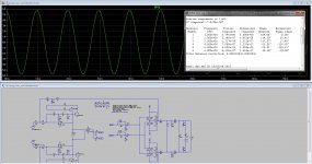
I have done some sims with the russian version and the audiamp from ir.
The transistor limmiter in error amp do rise distortions, because of transistor capacitances, it go from 0.00011 to 0.008 procent, I did use the simpel two transistor version. Yes I know in real work it quite different, the switch models are perfect, I do try it in a model of the power comparator or the IR2010 model to see different, with good coil and caps we can get low distortion with pre feedback.
The UCD can be made very good, but the trianle carrier version also can be quite made better with good parts, a current feedback version is more difficult because of the low pass fase shifting, also post feedback has om the same reason trouble, it shifts the fase, a bessel lowpass do not, maybe that is possible burt then we have not constant amplitude behavior, but fase stays oke.
For such simple technology, it is quite complicated to get a real lineair modulation scheme.
regards
Attachments
Last edited:
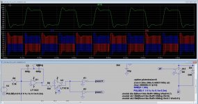
If you want open loop, no feedback, make multiple voltage level class D.. reduces THD very much , and without feedback. Now we have 2 voltage levels PWM signal. we could have many voltage levels, for example 6...
I only omplemented classical UCD in real design long time ago. I did simulated in spice this "oersted paper" versions, but was not satisfied with stability. I actually contacted the autor of this "Oersted Univerity " paper, we had some chat over email. He says this is just his approach, and he agrees that Bruno's Hypesx and UCD+ does not use this method for sure, and that he does not know what method Hypex use becase it is a secret and every hypex amplifier comes with "epoxy glued" electronics. So in Russian forums, I would say they "crached" real Hypes design (using those transistor network for stability). Actually I never tried this design, I am not sure how this transistor networks kills additioanl poles/ zeroes to prevent amplifier to oscillate on different frequency.
But Bruno in his papers mentiones "transistor network" for kissling additioan l poles and zeroes when modulation is high to prevent unstability (something like that)
I am sure DATASHEETS, and MANY ZEROES in THD like 0,001% SELLS hypex. And I am also sure that classic most simple UCD (from Brunos patent with 0,1 % THD from 20 khz to 10 khz (frequency independednt) ,and with VERY stable transient response (square input) and with alsmost 100 kHz bandwidth (no phase shift in audio range) SOUND maybe better then all those 0,001 % amplifiers. 0,1% THD CAN not be heared , but phase shift in audio range and instability of amplifier can.
None of those is not mine except spice schematics which can be used for faster simulation (using logic blocks).
Using most simple feedback like classic UCD (from patent) and multiple level PWM modulaton could achieve 0,01% and GREAT stability. Or using this UCD+ hypex "Russian method"
Multiple level is more close to real signal, and VERY small LC filter is needed. Output voltage (a) C 1/4 440 mF (b) C 1/4 1:32 mF.
I wonder would it be possible to make post filter feedback (UCD type) using multiple level PWM modulation. (phase shift)
Last edited:
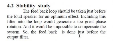
When I refer to "complicated design" I refer to post filter feedback described in "Oersted Univerity paper" IRF version is prior to filter feedback, it is hysteretic class D. I want LC filter to be part of feedback not free outside 🙂
Feedback is a must.. feedback makes class D low THD. Ideally PWM modulation and demodulation is ZERO THD, mathematically ideall.. But mosfet switch is not ideal due to dead time. If you hate feedback, then make multiple level PWM class D
Feedback is a must.. feedback makes class D low THD. Ideally PWM modulation and demodulation is ZERO THD, mathematically ideall.. But mosfet switch is not ideal due to dead time. If you hate feedback, then make multiple level PWM class D
Please send spice file, not just image, so I can try to simulate also. Also I have very little time lately for class D (just not to waste time drawing in spice which I am very low) 🙂
I dont see schematics good in those screenshots: But this is not "russian version" I see only pre filter feedback version, not post filter feedback.. ?!
I would say that D class when LC filter is outside feedback is not good ?!! In originall UCD you can have 2- 100 ohm load, and LC filter characteristics can not be seen on the output signal near 20 khz..
Hi Grizlek, thanks for all the thoughts for class d amps technology, on the paper with all the zeros making things unstable is also a transistor network, what it does is keeping the carrier on his place when drive ot almost to the rails, and when harder it klips and stops oscillating, then probe the mosfet and see it there are big currents, last i did one and have no big currents, it keeps quite oke in timing.
Biggest problem with a LC filters is the fase shift in time, keeping a proper feedback lets the switching modulater shifts in time also to keep track, I agree the dampingsfactor is much lower and the rail rejection is poor, however these days we can make a good supply easely, the modern switching can me made fast when take attention with the feedback network.
Here leapfrog did one, using a transistor network.
What you mean with multiply modulator system is like a 3 level one? these seems to have crossover, the solution then is inject very small pulses with a clock on the zero passages of the output carrier.
No it is not russian versions, I have included a zip with more types of amps so you can see yourself. I have drawn the russian one tough but do need to now the differential opamp used.
thanks.
regards
Attachments
Last edited:
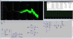
When include the coil, maybe when use 100Khz bandwidth we have no trouble, and using a 2 pole bandpass bessel type filter to delay for the carrier frequency.
I have seen the multipole designs, to complicated, a three level with injected small pulses for the crossover removal is a nice one.
The test of the output coils, when using a 30Khz 12 dB one give higher distortions then the 100Khz 24dB version, looks very nice, and with such high dropoff the feedback is better organized.
class D is quite wide what concerns quality sound, so much parts influences.
Pictures is with and without postfeedback.
regards
Attachments
http://www.ti.com/lit/ds/symlink/tas2770.pdf
This is not for 'real audiophiles' becouse:
- It lacks analogue inputs (you cannot put your fancy stuff between source and amp anymore) .
- Power is limited to circa 10-20W (you will not be able use it as a heater in winter conditions or to weld speaker cables with 1kW RMS power).
- It's dirt cheap, too small, to little external components (you have no place to put WIMA's and Coilcraft).
- You cannot solder it at your workshop.
But...
- It uses PFFB loop with I/V kelvin sensing at the outputs.
- Declares 32 uV A-weighted output noise.
- Low and clean THD+N versus power .
- Finally beautifully consistent THD+N versus frequency.
- 90 dB worst-case PSRR.
- I2S input so you can do what you want with DSP before it.
Audio performance is on pair with NCxxxMP modules at least not the power. I am curious what about the sound?
Lovely solution for portable battery-powered or compact, low-power systems.
Last edited:
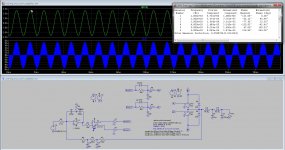
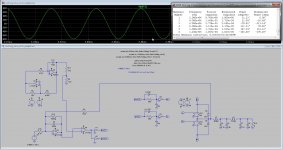
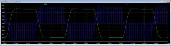
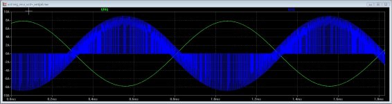
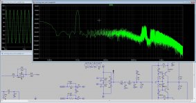
I have done some sims, but the UCD version and the delta sigma are the best, delta sigma is even without postfeedback low in distortion.
Here some results, also with squares, maybe time to duild one to see and discover the sound, I am curious about this technology.
Nice to see that current trough mosfets looks the same as with a stereo coder for fm hehe, much more liniair here..
regards.
Here some results, also with squares, maybe time to duild one to see and discover the sound, I am curious about this technology.
Nice to see that current trough mosfets looks the same as with a stereo coder for fm hehe, much more liniair here..
regards.
Attachments
Last edited:
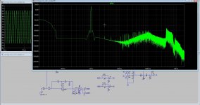
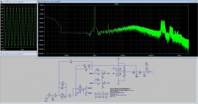
Part two, was out of time here.
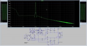
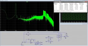
I did use 24dB octave filters on output, then can use low switchfrequency who is better for linearity, these two types of class d do quite wel, include the coil in feedback give indeed more control who you can see on the sqare test.
Make myself a power comparator and modulator on separate board for testing, if this do not make trouble afcourse, using coax for signals help.
The little peak on 3 Khz is proberly from sim and not present in real.
Attachments
Windforce85 noted:
Great addition to an all digital system.
Perfect for tweeters and high eff mids!
"Description
The TAS2770 is a mono, digital input Class-D audio amplifier optimized for efficiently driving high peak power into small loudspeakers. The Class-D amplifier is capable of delivering 15.4 W of peak power into a 4-Ω load while sustaining 11.6 W continuously with less than 0.03 % THD+N at a battery voltage of 12.6 V.
Integrated speaker voltage and current sense provides for real time monitoring of loudspeaker behavior. A battery tracking peak voltage limiter with brown out prevention optimizes amplifier headroom over the entire charge cycle of 2S or 3S battery systems. Up to eight devices can share a common bus via either I2S/TDM + I2C."
This needs ... a thread!
Cheers,
Jeff
Windforce85 noted:
Great addition to an all digital system.
Perfect for tweeters and high eff mids!
"Description
The TAS2770 is a mono, digital input Class-D audio amplifier optimized for efficiently driving high peak power into small loudspeakers. The Class-D amplifier is capable of delivering 15.4 W of peak power into a 4-Ω load while sustaining 11.6 W continuously with less than 0.03 % THD+N at a battery voltage of 12.6 V.
Integrated speaker voltage and current sense provides for real time monitoring of loudspeaker behavior. A battery tracking peak voltage limiter with brown out prevention optimizes amplifier headroom over the entire charge cycle of 2S or 3S battery systems. Up to eight devices can share a common bus via either I2S/TDM + I2C."
This needs ... a thread!
Cheers,
Jeff
The all digital versions are not a really future, switching problems and noise and not high power, however small amps with very fast mosfets who can do work in the Mhz region, sigma delta or direct digital can be done, but then with this high switching we still need quantization and oversampling to get noise out of audio band, and so it get quite complicated, exception is a self oscillation sigma delta who do let seen very low distortion..
For smal amps like these it do work as says the paper with quite low distortions, and yes a all digital active 3 way system is nice, for use with the single point horns who need delays,, we can make a class d who do delay from itselfs.
nice stuff for learning.
regards
Last edited:
I wish all the people here, the world, nature and animals an happy and yet very important a better newyear, 2017 was not one of the best, better it was the worst ever.
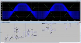
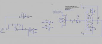
here I did a full bridge, with a single ended input, a trhee level is also option, but then we need pulses on the zero transistions otherwise we get crossover distortions, we can clock these pulses and inject them there, did see something about the a while ago, do not now where.
The full bridge does supress the even harmonics but I see more uneven harmonics with it, of this sounds bad I do not now, mine ciclotron has also this problem, it is due of balanced technology.
regards
Attachments
Today when get sober again from al that beer and stuff, I did some hobby here, trying a transistor feedback bridge who do have kind of proportional feedback, it does change feedback with signal voltage, I think Ncore is such a way, as Frizlek did mention if I remember.
The feedback hysteric bridge is from a old paper, adjusted for here.
There is a low distortion and stability even when driven very hard, when signal is high feedback get,s lower, it keeps the carrier quite on his place.
Overdriven it do stop the oscillation of the amp, but do not see uge amps, only a square..
polarity of signal is important for right working on feedback, so it stays negative otherwise it go osclillate on 3 Mhz. when keep capacitance low in this bridge it will
regards
Attachments
"Better" is not always "better".
More details please.
But if it needs to be a class d you can`t go wrong with this one:
Sure Electronics AA-AB32313 2x400
More details please.
But if it needs to be a class d you can`t go wrong with this one:
Sure Electronics AA-AB32313 2x400
- Home
- Amplifiers
- Class D
- What Class-D amp give best sound?