Damir, there is nothing wrong. Cascode may reduce Miller capacitance but the base current is still there. CFA has partial compensation of base currents.
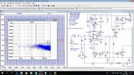
Hi Damir,Here is simulation to show input distortion with input resistor of 0.1R and 1k.
Used Cordell's models.
Do I do something wrong here?
Damir
Added input distortion of my CFA.
this is indeed surprising. Always thought that balanced impedances at non-inverting and inverting inputs give best results.
But I'm wondering about the DC balance in your circuits. The inverting input sees about 20k (DC), while the non-inverting input sees 0.1||20K or 1k||20K. What does happen, if you balance the DC pathes?
Kind regards,
Matthias
Damir, there is nothing wrong. Cascode may reduce Miller capacitance but the base current is still there. CFA has partial compensation of base currents.
Dimitri, I was wondering why Cordell can't confirm D. Self input distortion not why there is one even if cascode was used in the bjt LTP.
What surprised me more is input distortion with the fet cascoded LTP I mentioned some posts back.
Last edited:
Hi Damir,
this is indeed surprising. Always thought that balanced impedances at non-inverting and inverting inputs give best results.
But I'm wondering about the DC balance in your circuits. The inverting input sees about 20k (DC), while the non-inverting input sees 0.1||20K or 1k||20K. What does happen, if you balance the DC pathes?
Kind regards,
Matthias
Matthias there is DC balance, 1k resistor is in series with capacitor.
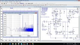
It depends on how you cascoded itFET LTP bootstrap cascoded with CM. Very similar to first case. That one surprised me, I expected much lower input distortion??
It depends on how you cascoded it
Attached my TT amp with the fet bootstrap cascoded LTP.
Input distortion is dominate distortion in this case(0.000329%), THD20 is below 1.5 ppm with low source output resistor.
Attachments
In my understanding, base current of inverting input flows via 20K, while base current of non-inverting input flows via 0.1R||20k or 1k||20k in the second circuit. So I would expect some effective offset voltage, depending on bias currents.Matthias there is DC balance, 1k resistor is in series with capacitor.
Matthias
In my understanding, base current of inverting input flows via 20K, while base current of non-inverting input flows via 0.1R||20k or 1k||20k in the second circuit. So I would expect some effective offset voltage, depending on bias currents.
Matthias
OK I got it. Normally there is serial capacitor in the input here removed to simplifies the FFT. If you want DC connected input you would need DC servo.
This unbalance does not influence input distortion.
Last edited:
But why do we see more high-frequency residuals in circuit B than in A? I assume that it stems from the output stage.This unbalance does not influence input distortion.
Still wondering whether you make a comparison where everything else is kept the same, save the input resistor at non-inverting input.
Matthias
Hi Damir,
just made a quick experiment with my nested MC amp, BJT-input version from post #80 in the thread there.
I have always used balanced impedances for feedback network and network towards input source. If I now replace the input network with a lower-impedance one, then input distortion becomes worse. This is also true, if I just place lower-impedance R+C combinations across the original resistors, such that all DC conditions remain the same.
So your results really surprise me.
Kind regards,
Matthias
Last edited:
Matthias what surprise you? I just did quick simulation because Cordell said he can't get that increase of input distortion Self described on his book.
I was surprised I can simulate it and Cordell not and asked if I do it in wrong way.
I was surprised I can simulate it and Cordell not and asked if I do it in wrong way.
It might be better to conduct the experiment with only series resisters at each input. The sources are low enough impedance to supply bias current.
You might have to compensate for unity gain.
You might have to compensate for unity gain.
I always thought that balanced impedances are good for distortion performance of the differential pair, since then the nonlinearities in both halves have the same influence, if transistors are identical as in simulation.Matthias what surprise you?
Furthermore, this is confirmed by simulation experiment with my own amp.
Your result suggests that it is better to have a very low impedance on one side. I'm surprised because I do not understand the difference between your and my experiment.
Matthias
I cannot give a reference where this believe in impedance symmetry stems from. Maybe, it was my own idea without ever really questioning it. Until now, it worked well. But if your results are true, then I have one more place to improve my design. It will never be built ... ;-)
Matthias, balanced impedances are good for distortion performance of the differential pair, but not important in this discussion about input distortion.
I just want to be sure if Self is correct, and in mine opinion he is.
I just want to be sure if Self is correct, and in mine opinion he is.
Damir, can you explain or provide a pointer to a post describing: How does one separate these both contributions in a simulation experiment, distortion due to unbalanced impedances and distortion due to nonlinear voltage-drop across a resistor at the non-inverting input?
Thanks,
Matthias
Thanks,
Matthias
Bear in mind that the circuit I simulated was quite close to the one that Self was referring to in his book where he discussed the input current distortion. If you simulate a "better" circuit whose base distortion at 1kHz or 20kHz with a low-impedance input, and get significantly lower base distortion, then you may see increased distortion due to the inclusion of a 1k source resistance.
All I am saying is that I was unable to duplicate his results with a circuit that was very similar to his.
Cheers,
Bob
All I am saying is that I was unable to duplicate his results with a circuit that was very similar to his.
Cheers,
Bob
The baseline seems to be the problem, at least can I confirm that for the "think model" of impedance symmetry between the inputs.If you simulate a "better" circuit whose base distortion at 1kHz or 20kHz with a low-impedance input, and get significantly lower base distortion, then ...
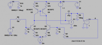
In the simple conceptual model below (ULGF around 600kHz, V4 ensures small sim step), one gets lower THD, if R2 and R8 at non-inverting input are scaled down. I have also checked that e.g. collector voltages of Q1 and Q2 remain in balance after that change.
In my amp with much less distortion, this does not hold. Best performance is achieved with balanced impedances.
Sorry for the noise and any trouble, Damir.
Cheers,
Matthias
Attachments
Would someone who's entered Self's exact design in an .asc file please post it if they are willing? I'd like to take a look at it and I don't have Self's book.
TIA
TIA
Older transistors that were used for the LTP in the past had worse Hfe and/or worse Vaf as well as worse Cob. All these contribute to static input distortion. The BC550C is really an excellent transistor compared to some of the others that have been used.
Just throwing that in there, it probably doesn't account for the majority of distortion in any of the examples here.
Just throwing that in there, it probably doesn't account for the majority of distortion in any of the examples here.
- Home
- Amplifiers
- Solid State
- Bob Cordell's Power amplifier book