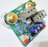
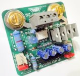
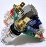
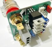
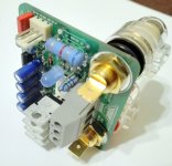
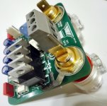
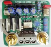
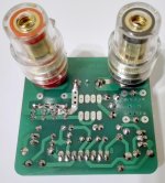
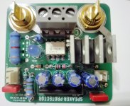
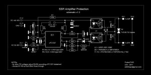
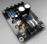
Speaker protector based on uPC 1237 HA , VSSA-V621 and MOSFET ")
Attachments
-
 IMG_20171128_201709.jpg345.2 KB · Views: 1,061
 -
 IMG_20171128_201715.jpg416.3 KB · Views: 974
 -
 IMG_20171128_201725.jpg436 KB · Views: 937
 -
 IMG_20171128_201754.jpg407.7 KB · Views: 873
 -
 IMG_20171128_201804.jpg435.4 KB · Views: 828
 -
 IMG_20171128_201812.jpg493.5 KB · Views: 190
 -
 IMG_20171128_201822.jpg626.4 KB · Views: 246
 -
 IMG_20171128_201855.jpg411.4 KB · Views: 306
 -
 IMG_20171128_201827.jpg657.6 KB · Views: 323
Hi Alex, that looks very good. I have some of the chips on the shelf. Would you post the circuit?Speaker protector based on uPC 1237 HA , VSSA-V621 and MOSFET
regards Olaf
Hi Alex, thank you very much.Thanks, schematic attached .....
regards Olaf
Thanks, schematic attached .....
Nice.
But what is the time delay from DC detected until the Mosfets actually disconnected the speaker ?
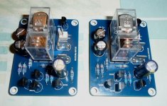
The measurements made on the "damping factor" give better results with the mosfet version than the version with a good relay and the switching time is faster (same schematic).a humble relais ia better choise and very reliable
Attachments
I have done measurements on the "damping factor" that are better but I do not say that listening can make a difference.
The model I use is in place on a USSA-5 (15-20W class A) and listening no problem of sound reproduction (distortion) so I can not say for high power and not having measuring device I can not comment on the THD.
For SSR protection it is very important to polarize the optocouplers (the maximum current possible) and not just use one (two in parallel) to control the mosfets which must also be chosen with a "rdson" as low as possible, otherwise there is more interest in this type of scheme.
This is only my humble opinion.
Project16
Totally agree !! SSR is very good, but the key to the ultimate amplifier is in small details.
Take any amplifier project and make it 100% perfect in details, connections, PCB, wiring, earthing, etc.
I think that schematic is only 30-40% of the total score. Very good amplifier project can be destroyed with bad wiring and big amount of cheap connectors.
Short, low resistance path from the amplifier to the speaker is very important.
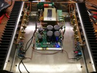
With SSR protection I went a bit further, I have placed it in PSU, very close to the most hefty earth point in the amplifier. In my amplifers I started to remove all unnecessary connectors I can, I am using only 3cm of speaker cable per channel and output is going directly to the speaker (so we have good few cm of cable less + less connections inside enclosure). Bellow my 2x 100W amplifier fully wired up.
Damping factor is not only the RdsON or relay, often there is 2-4 connectors on the way (they adding a bit of the resistance, after long time of usage connection resistance goes higher).
Totally agree !! SSR is very good, but the key to the ultimate amplifier is in small details.
Take any amplifier project and make it 100% perfect in details, connections, PCB, wiring, earthing, etc.
I think that schematic is only 30-40% of the total score. Very good amplifier project can be destroyed with bad wiring and big amount of cheap connectors.
Short, low resistance path from the amplifier to the speaker is very important.
With SSR protection I went a bit further, I have placed it in PSU, very close to the most hefty earth point in the amplifier. In my amplifers I started to remove all unnecessary connectors I can, I am using only 3cm of speaker cable per channel and output is going directly to the speaker (so we have good few cm of cable less + less connections inside enclosure). Bellow my 2x 100W amplifier fully wired up.
Damping factor is not only the RdsON or relay, often there is 2-4 connectors on the way (they adding a bit of the resistance, after long time of usage connection resistance goes higher).
Attachments
Last edited:
I found another version using Mosfets increased the distortion considerably. Have you actually tested this at various powers at various frequencies for THD?
-Chris
I found the source of the distortion in that protection system. It came from the control transformer being mounted directly over the mosfets and optocoupler. The NS series boards with on board mosfet relays measure excellent.
Once my machine shop is back in running condition I hope to put a few different amps together for testing again. We can test the circuit again then. That first VHex amp you measured used a basic version of the same protection system with the same mosfet relays. That one measure excellent!
That can certainly throw off time frames. Let's see what happens, just 'cause.
I'm just going off experience from seeing similar things done while doing my phone guy gig. We would typically be called in emergency style to run cables and install jacks. Is he going to include a phone in there? A paging speaker in the ceiling - assuming a drop ceiling with lights.
-Chris
I'm just going off experience from seeing similar things done while doing my phone guy gig. We would typically be called in emergency style to run cables and install jacks. Is he going to include a phone in there? A paging speaker in the ceiling - assuming a drop ceiling with lights.
-Chris
- Home
- Amplifiers
- Solid State
- Post your Solid State pics here