
Hello greierasul: Tell me, what is the difference between the 2012 and 2016 version ?The prototype-ptil 😛
I am new to diy amplifiers and learning and as far as I can tell, the version POP ALEXANDRU has from 2014 is - I guess - based upon the 2012 version. What changed or why do it need to change ?
Oneminde
In 2012 was a more complex schematic. It is harder to build SARA-2012. For these reason I redesign the schematic, I simplified it. The result it is SARA -2016. All the variants from this topic are based on SARA-2016. So, I recommend you this road. SARA-2012 it is a closed road.
Thanks, I want to put one together. I know the 2SC5200 / 2SA1943 is suppose to be excellent and SARA-2016 seem like a good starting point.In 2012 was a more complex schematic. It is harder to build SARA-2012. For these reason I redesign the schematic, I simplified it. The result it is SARA -2016. All the variants from this topic are based on SARA-2016. So, I recommend you this road. SARA-2012 it is a closed road.
Couple questions, I was hoping you could answer?
1) Why does Alex's PCB have MJL3281/MJL4302 - I don't think those are complimentary pairs, right? Shouldn't it be MJL4281/MJL4302, or MJL3281/MJL1302?
2) Why does Vlads use 2SC5200/2SA1943?
Is there differences other than the mosfet choice I'm missing, or just a preference.
Seems like the 2SC/2SA are lesser mosfets - less voltage max?
I'm sure I am missing some very compelling reasons one was chosen over the other, so I was hoping someone could explain.
1) Maybe was an Alex typo. You must to choose the complementary pair. You are right.
2) You can choose any power bipolar complementary pair transistor with 30Mhz Ft. Alex use mjl4281, Vlad use 2sc5200, I use here TTC5200. For all that three different pairs, the schematic meets design requirements.You can choose the cheapest or you can choose the stronger. Generaly speaking, I preferr the smallest Cob transistor.
2) You can choose any power bipolar complementary pair transistor with 30Mhz Ft. Alex use mjl4281, Vlad use 2sc5200, I use here TTC5200. For all that three different pairs, the schematic meets design requirements.You can choose the cheapest or you can choose the stronger. Generaly speaking, I preferr the smallest Cob transistor.
Last edited:
Yesterday I was listening SARA-2016 for an hour with Naim DAC V1 on the Revel Performa3 F206 loudspeakers. The sound was excellent. Very rafined and revealing. No one instrument mixed with another.
I don't know If I've listened to the Toshiba transistors (2SC5200/2SA1943) or the ones you are using TTC5200/TTA1943. I know they are popular, but now that there is a list of transistors and options, I do wonder how they compare to one another. Only way to find out is to try them and that can be done during construction and experimentation phase.
@ bullittstang: One might see the transistor swapping or choice as "tube rolling". They will sound different and only way to make sure one pick the right transistor - besides values - is to listen to them.
@ bullittstang: One might see the transistor swapping or choice as "tube rolling". They will sound different and only way to make sure one pick the right transistor - besides values - is to listen to them.
I suppose, all the transistors will sound almost the same. The differences between them will be very small, almost inaudible.
Since I am wondering, I thought I would ask: Is this a power distribution board ?The prototype-ptil 😛
Since I am wondering, I thought I would ask: Is this a power distribution board ?
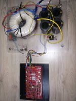
I do not understand very well what did you say but I will trying an answer. In the picture we have one amplifier module on the heatsink and an extempore power supply. Soon, we will have a definitive amplifier.
I understand. The reason I asked was because I did not see the transistors, but I inspected the picture and can now see that they are mounted underneath the PCB. Rather unusual placement but works I assume.
Looking forward to the more finished version and measurement 🙂
Looking forward to the more finished version and measurement 🙂
There are two PCB versions: one from Alexmm and another from VladPalade. Alexmm version has the power transistors outsides of the PCB.
I see. I am leaning more towards the classic design where the transistors are placed on the edge, simply because the thermal issues (heat) can be taken care of in a better way. Any heat on the PCB is bad and will cause heat issues in resistors and such. Naturally, one can place such components far away, letting all the components "breath" - but this has nothing to do with the overall schematic and function. Each to ones own.
So as I said, looking forward to your finalised version and when I have the opportunity, produce my interpretation and present it 🙂
So as I said, looking forward to your finalised version and when I have the opportunity, produce my interpretation and present it 🙂
Since its the beginning of 2018 I thought it would be a good opportunity to check the progress greierasul ?
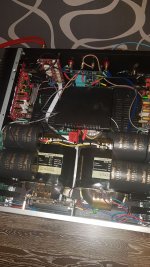
Almost done.
You put some High-End quality components into this amp.🙂
The amplifier has to run on the 10k dollars speakers. The owner does not allow any weakness in the acoustic chain. The room where will play this audio system will also be acoustically treated.
Looking good and the parts are premium select 🙂The amplifier has to run on the 10k dollars speakers. The owner does not allow any weakness in the acoustic chain. The room where will play this audio system will also be acoustically treated.
Q: Will you post construction pictures of that one, as in a series from start to finish ?
- Home
- Amplifiers
- Solid State
- SARA-2016