And raise distortion too thanks to non-linear capacitance.That will reduce the bandwidth.
I have been simulating supply rejection by putting ac sources in series with the supplies and have found the R3 47k is not the main weakness. The -ve rail is much worse (18dB PSRR at 100kHz), requiring a filter on the supply to the signal transistors.
Yes it would. The simulation of increasing these is a bit unexpected. 1k is fine while 2.5k and upward shows as increasingly unstable. At less than 10k and you have an RF transmitter. I wonder just how well gate capacitance is modelled on these.
When I have time I will try Ian Heggluns models for this amp.
When I have time I will try Ian Heggluns models for this amp.
Attachments
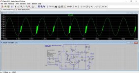

The -ve rail is much worse (18dB PSRR at 100kHz), requiring a filter on the supply to the signal transistors.
Injection (in varying degrees) from the negative rail seems a feature of most designs tbh.
Modelling is simplistic, but very high resistance to the gate will make an oscillator. The resistor is too high a value to damp the transmission line tuned circuit that exists at the gate with device capacitance and package inductance.Yes it would. The simulation of increasing these is a bit unexpected. 1k is fine while 2.5k and upward shows as increasingly unstable. At less than 10k and you have an RF transmitter. I wonder just how well gate capacitance is modelled on these.
For the same reason you can use ferrite beads (lossy), but should never use inductors to the gate.
Thanks, that makes a lot of sense.
Ian's models were broadly similar in simulation. Again, tweakers paradise... cut that 6n8 out and its good with 20k gate stoppers.
Ian's models were broadly similar in simulation. Again, tweakers paradise... cut that 6n8 out and its good with 20k gate stoppers.
Interesting in the STA-2200 schematic, the 'low level signal' grounds are connected to the main ground trace through C704a (0.1 uF). Is this a good practice? Many amps I've seen on this site now couple the two grounds using an ~10 ohm resistor and a pair of antiparallel diodes. Would this be a good mod for the Realistic?
Steve.
Steve.
Using low value caps to tie grounds together is something that used to be a seen a lot on TV chassis'. Always got the feeling they were just trying to cover all scenarios for the ingress of interference. Often caps would be marked on diagrams but not fitted in production, or fitted for certain geographical markets.
I'd be curious to know what voltage is measured across R9 in the actual circuit.
With 50V rails I estimate 7mA through it and 85V across it. If so, TR3 collector is just 13V or so above the neg rail. That's restricting the TR3 current swing to a little over 1mA before it saturates. That can't be good.
Got the amps powered up today, Good news is they didn't go Bang 🙂 Bit of smoke ..... Forgot to remove the PSU Discharge Resistors 🙄 Bad news is that the DC Offset has virtually doubled on both amps for some reason, from something like 11mv to 25mv and 17mv to 40mv, although this might not be entirely accurate, I have a 1mhz spike coming from somewhere, I originally thought it was my Grid Tied Inverters, I have 1100w of solar panels a few feet above from where I'm working, turned them off, disconnected the solar panels, but the spike is still there, even with the amp turned off, seems like the wires to the dummy loads is acting as an antenna, so not sure where this spike is coming from, I saved the waveforms onto a usb stick, but they were saved as .wfm Format, and I can't find anything to open or convert them with at the moment.
R9 I took some measurements while waiting for the bias to settle, so this is with no load on the outputs.
Voltage Across R9 (76.2v)
WRT to 0v and the IN4001 end of R9 (47.5v)
WRT to 0v and the Collector of TR3 (-29.1v) - Pretty sure I didn't have the probes reversed !
If I get chance tomorrow I'll check again, but I'm away for the weekend so might have to wait until Monday.
Last edited:
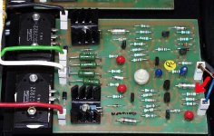
also nice that they chose low capacitance transistors for the differential VAS/current mirror.
when i played with this circuit MANY years ago (I believe I first saw it in Transactions in Consumer Electronics in 1977, the first time I heard of lateral MOSFETs!), the choice of parts there had significant impacts on stability, etc.
mlloyd1
when i played with this circuit MANY years ago (I believe I first saw it in Transactions in Consumer Electronics in 1977, the first time I heard of lateral MOSFETs!), the choice of parts there had significant impacts on stability, etc.
mlloyd1
That is very similar indeed to the basic circuit but with much more attention paid to decoupling and so on. Notice how high the gate resistors are.
Because when Maplin released their design, simulators of the quality of LTSpice just didn't exist. There were a few expensive commercial products, but even they had very crude libraries and would have been much less useful.
Well I can vision a tech guy with a huge drawing board laying out the circuit, and once a module was built, a group of guys around a scope looking at how different parts affected the output and performance, and I would have thought some pretty extensive testing both reliability wise and sound quality wise before releasing it for sale, though I can't see it running at the quoted specs for very long before something pops !
The drawing board bit is correct, hence the bodged hand drawn PMOS symbol.Well I can vision a tech guy with a huge drawing board laying out the circuit, and once a module was built, a group of guys around a scope looking at how different parts affected the output and performance, and I would have thought some pretty extensive testing both reliability wise and sound quality wise before releasing it for sale!..
PCB design would also have been by tape out.
Knowing the magazines, "group of guys" is optimistic. More likely "No smoke" and publish.
The Realistic doesn't have the 47R - I am thinking it was a mistake and should have been in series with RV1 until somebody found out just how low RV1 had to go for 50mA with some mosfets. RV1 1k was too high anyway, worst case 500R is more than enough
It also has heavy -ve rail filtering - probably too much as it reduces output swing
I have a 1mhz spike coming from somewhere, I originally thought it was my Grid Tied Inverters, I have 1100w of solar panels a few feet above from where I'm working, turned them off, disconnected the solar panels, but the spike is still there, even with the amp turned off, seems like the wires to the dummy loads is acting as an antenna, so not sure where this spike is coming from
Probably your local AM radio transmitter. I always get an 828KHz tone, from the local ABC Midwest & wheatbelt 10KW 828KHz transmitter.
The two capacitors on the second LTP between base and collector I found to be just on the edge of oscillation, or it was on my Maplin amp.
When I redesigned it I increased them a little and got better stability.
The design is a compromise between bandwidth and stability.
When I redesigned it I increased them a little and got better stability.
The design is a compromise between bandwidth and stability.
You can actually reduce the capacitors C5 and C6 by adding a couple of pF from RV1 to the base of Q2. Increasing R13 & R14 does not help loop stability, they are for Q6 and Q7 as standalone devices
Yay it still works! As expected. 😎R9 I took some measurements while waiting for the bias to settle, so this is with no load on the outputs.
Voltage Across R9 (76.2v)
WRT to 0v and the IN4001 end of R9 (47.5v)
WRT to 0v and the Collector of TR3 (-29.1v) - Pretty sure I didn't have the probes reversed !
That's 6.35mA through R9.
Are your rails +/-50V? If so, that leaves about 19V headroom on TR3 collector or 1.6mA.
I'd be inclined to change R9 to 8.2k 1W and C4 to 10nF polypropylene to get TR3 & TR4 collectors at a closer voltage.
That might be good news in a way because The mismatch between R2 & R7 should cause an excess positive dc offset. So it might be measuring as expected now. The fix is to try 33k for R2.Bad news is that the DC Offset has virtually doubled on both amps for some reason, from something like 11mv to 25mv and 17mv to 40mv, although this might not be entirely accurate,
Why it was designed with R2 different from R7 is not clear to me. There must have been a reason.
25mV is negligible. R2 is 47k because almost all amplifiers were that value, no good reason. R1 2k2 is a bit high and causes extra distortion, see Doug Selfs blameless articles
4.7k. I guess Naim Audio never read Self's books. That might explain their success 
Attachments
Last edited:
Very similar indeed. Some values changed but essentially the same. The difference that stands out for me is the omission of C6. Curious.I apologize it this doesn't fit here, but I'd like to show a very similar circuit.
But bigger C5 and there is also a 5pF across the 22k feedbackVery similar indeed. Some values changed but essentially the same. The difference that stands out for me is the omission of C6. Curious.
- Home
- Amplifiers
- Solid State
- Any Maplin MosFet Amp Guru's on here?