If you are taking the amp on the road or otherwise subjecting it to heavy vibration you might want to stick the polypropylene caps to the pcb using a small blob of silicone or glue gun.
Good Idea, although they won't be doing any traveling, I'm interested to see how they stack up against my Quad II Mono Blocks after I've built the Rod Elliot Pre Amp and Phono (RIAA) Pre Amp, I think the Quad 22 control unit lets things down, but that's a story for a different thread 🙂
Because when Maplin released their design, simulators of the quality of LTSpice just didn't exist. There were a few expensive commercial products, but even they had very crude libraries and would have been much less useful.Strange after 35 years plus, these little things are being noticed, and In some cases addressed.
C4 is a mystery...why the rather specific value of 6.8nF?
R12?
Another spin on it 🙂
Think of R12 as providing the base bias current to turn on the current source (TR5). Almost 10ma flows which is a bit excessive. Lets make R12 a 30k and ensure TR5 is a high gain device. That cuts the dissipation.
Do we need TR3 ? Lets remove it and link it out.
Is R10 helping or not ? I would say not. Its reducing the transconductance of that stage. Lets link it out.
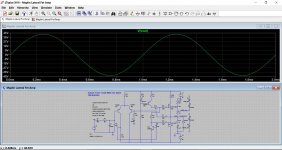
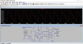
Switch on. What happens ?
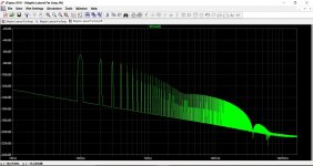
It works. Outwardly and not a lot changes. DC offset is a bit higher but that could be addressed. All is stable.
Attachments
Is R12 still needed, in the 90's Maplin article they even mention VR1 being connected between the collectors of driver transistors as if R12 didn't exist, and with no further mentioning at all of its role.
Does R12 really minimize start-up thump as earlier mentioned in this thread?
Does R12 really minimize start-up thump as earlier mentioned in this thread?
R12 doesn't appear to serve any useful function. Wouldn't like to say on start up behaviour tbh.
The listening averages are indeed very low.There is a lot of talk about maximum power and SOAs.
In reality a big amplifier is not normally ever subjected to max power RMS.
Very loud can be as little as about 10W with plenty of headroom for brief crescendos.
I actually measured the power going into my speakers at very loud from a 100W amplifier and it was only 6W RMS.
The peaks of the transients on the other hand can be very high.
That's why many of us allow for peaks that are 20dB above our average listening levels, in the hope that the transients don't get clipped. Clipping is quite common. That's where the amplifier has been asked to output MORE than it's rated maximum.
That 20dB ratio between average and peak only allows for a ten fold increase in signal voltage. I believe some music can go beyond 30times on voltage ratio (~+30dB).
I typically use <1W for adequate or normal listening averages. But I build ~100W amplifiers. There's my 20dB for the transients.

TR7 symbol is incorrect.
The gate is upside down. The drain and source labels are correct.
The drain and source symbols/lines/arrow are correct.
The gate is upside down. The drain and source labels are correct.
The drain and source symbols/lines/arrow are correct.
Has anyone commented on the symylarity between this "Maplin" and our Forum's Symasym and Roender amplifiers?
Note in both of these that R12 has been replaced by a grounded common base transistor (Q10 in the Roender).
Note in both of these that R12 has been replaced by a grounded common base transistor (Q10 in the Roender).
Attachments
Dave Goodman, bless him, didn't describe his circuit completely. No mention of R9, C4, R12.
I am tempted to wonder if R12 (47 ohm) was added to make the board layout easier. But why 47 ohm and not a wire link?
I am tempted to wonder if R12 (47 ohm) was added to make the board layout easier. But why 47 ohm and not a wire link?
The 47 ohm gives the impression of 'safety' when the preset is turned to zero ohms. There is 'something' still present between the two transistors.
I think you mean R9 = 12k. The Roender looks like something designed in a simulator! The double-differentiator, if you will, arrangement is common. But although it may seem a clever way to cancel distortion it actually brings with it extra problems that are rarely addressed. The Maplin circuit has some nice properties to it. I'm not sure this was by design or accident, tho.Has anyone commented on the symylarity between this "Maplin" and our Forum's Symasym and Roender amplifiers?
Note in both of these that R12 has been replaced by a grounded common base transistor (Q10 in the Roender).
You've turned it in to the more common, "RCA"/Naim type architecture. Single differentiator and simple Miller VAS. That will work. You introduce some distortion because the dynamic current to the upper FET goes through the variable resistor (RV1) but the lower FET is fed directly. In the Maplin circuit the current is fed equally(ish) to both FETs and the current through the variable resistor is constant(ish). In your circuit you would need to bypass RV1.Another spin on it 🙂
R10 in the original also reduces the transconductance, as you say. This reduces the loop gain and should help stability. Raising the loop gain is a mixed blessing because you have to be a lot more careful about stability. I think the Maplin design deliberately sacrifices feedback for stability. It's a cautious design. The pcb layout doesn't help it, though.
Last edited:
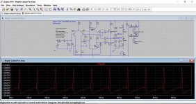
Use LTSpice and slightly overdirve the amplifier at 1kHz. You will see steps in the voltage on TR3 as C4 charges. Make it too large and the design latches after clipping for a while.
R9 (12k) limits current during clipping and improves recovery.
R4 (47R) is harder to explain. It might have been to modify clipping symmetry. The amplifier seems to work with it shorted
R9 (12k) limits current during clipping and improves recovery.
R4 (47R) is harder to explain. It might have been to modify clipping symmetry. The amplifier seems to work with it shorted
@Mooly
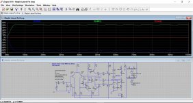
Try simulating the PSRR; it should be worse. The LTP current is modulated by the PS voltage across the 47k (because it doesn't use a CCS) and this will modulate the VAS current. In the original, the second differentiator mitigates this.
Try simulating the PSRR; it should be worse. The LTP current is modulated by the PS voltage across the 47k (because it doesn't use a CCS) and this will modulate the VAS current. In the original, the second differentiator mitigates this.

Realistic STA-2200 circuit similarities
I apologize it this doesn't fit here, but I'd like to show a very similar circuit. (Mooly, please delete this post if it is deemed as thread jacking).
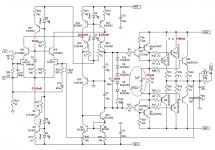
The Realistic STA-2200 receiver is from ~1980 and is rated at 60 W/channel using one pair of the Hitachi 2SK134/2SJ49 (running at ~+/- 48V). Although not the most powerful Realistic receiver produced, several have noted that they think this was the best sounding one they made. Stereo Review found the 1K onset of clipping at 65W (16 ohms), 74W (8 ohms), 97W (4 ohms) and 80W (2 ohms). THD was measured at .003% at 1W and 1K Hz, rising to .008% at 60W.
The amplifier section (shown below) is very similar to the Maplin one being discussed here.
Steve.
I apologize it this doesn't fit here, but I'd like to show a very similar circuit. (Mooly, please delete this post if it is deemed as thread jacking).
The Realistic STA-2200 receiver is from ~1980 and is rated at 60 W/channel using one pair of the Hitachi 2SK134/2SJ49 (running at ~+/- 48V). Although not the most powerful Realistic receiver produced, several have noted that they think this was the best sounding one they made. Stereo Review found the 1K onset of clipping at 65W (16 ohms), 74W (8 ohms), 97W (4 ohms) and 80W (2 ohms). THD was measured at .003% at 1W and 1K Hz, rising to .008% at 60W.
The amplifier section (shown below) is very similar to the Maplin one being discussed here.
Steve.
Attachments
That is very similar indeed to the basic circuit but with much more attention paid to decoupling and so on. Notice how high the gate resistors are.
Notice how high the gate resistors are.
That will reduce the bandwidth.
- Home
- Amplifiers
- Solid State
- Any Maplin MosFet Amp Guru's on here?