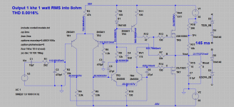
The 12k is the one that runs hot as it dissipates close to 600mW when the amp is running on the higher rail voltages.
I think they are talking about the resistor from the npn LTP to the mirror diode. That has about 70V across it in the original design and is running at about 500mW
R9 is 12k.
Thanks, that makes a lot more sense. 12k at approx. 5mA = 300mW. That's with 42V rails. Closer to 500mW with 50V rails.
I reckon its main purpose is to better balance the Vce across TR3 & TR4. It may have a less obvious secondary purpose...why is C4=6.8nF? 😉
So what is R12 for?
Thanks, that makes a lot more sense. 12k at approx. 5mA = 300mW. That's with 42V rails. Closer to 500mW with 50V rails.
I reckon its main purpose is to better balance the Vce across TR3 & TR4. It may have a less obvious secondary purpose...why is C4=6.8nF? 😉
So what is R12 for?
Why not 6n8 😀 Its a nice value and the colours looked good if you used the old Mullard C280 series.
R12, well that's another part that's up for debate. You can link it out with virtually no change on the dynamic performance of the amp, and virtually no change in DC currents in those stages. What does happen though is that TR3 sees a high static voltage across C and E the lower R12 is made. That increases dissipation in the transistor considerably.
So the 6n8 just keeps the the two ends of the 12k at the same AC voltage at HF which slightly 'improves' the open loop gain over 100kHz.
Why 12k? For the goal of matching Vces of TR3 & TR4 the supply voltage would have to be about +/-28V. For 50V rails the value is way wrong and I reckon it should be about 7k.
I'm not sure what the minimum psu voltage spec is for this amp.
I'm not sure what the minimum psu voltage spec is for this amp.
There is a potential start up glitch in the design. If the input pnp LTP starts hard over and lifts the base of the npn to 3.9V above the -ve rail, the npn would conduct 33mA if the 12k was not there or the capacitor across it large. The 12 k was chosen to saturate the npn at about 8mA
R9 is 12k.
Thanks, that makes a lot more sense. 12k at approx. 5mA = 300mW. That's with 42V rails. Closer to 500mW with 50V rails.
I reckon its main purpose is to better balance the Vce across TR3 & TR4. It may have a less obvious secondary purpose...why is C4=6.8nF? 😉
So what is R12 for?
The 12K has the sum of both rails across it.
It dissipates about half a watt.
Hmm. Possible. Shorting the output could also cause it. Needs simulating.There is a potential start up glitch in the design. If the input pnp LTP starts hard over and lifts the base of the npn to 3.9V above the -ve rail, the npn would conduct 33mA if the 12k was not there or the capacitor across it large. The 12 k was chosen to saturate the npn at about 8mA
A better solution would be a pair of diodes between the two input pnp collectors. Making the circuit behave well at clipping needs simulating also
I'd be curious to know what voltage is measured across R9 in the actual circuit.
With 50V rails I estimate 7mA through it and 85V across it. If so, TR3 collector is just 13V or so above the neg rail. That's restricting the TR3 current swing to a little over 1mA before it saturates. That can't be good.
With 50V rails I estimate 7mA through it and 85V across it. If so, TR3 collector is just 13V or so above the neg rail. That's restricting the TR3 current swing to a little over 1mA before it saturates. That can't be good.
There is a lot of talk about maximum power and SOAs.
In reality a big amplifier is not normally ever subjected to max power RMS.
Very loud can be as little as about 10W with plenty of headroom for brief crescendos.
I actually measured the power going into my speakers at very loud from a 100W amplifier and it was only 6W RMS.
In reality a big amplifier is not normally ever subjected to max power RMS.
Very loud can be as little as about 10W with plenty of headroom for brief crescendos.
I actually measured the power going into my speakers at very loud from a 100W amplifier and it was only 6W RMS.
I'd be curious to know what voltage is measured across R9 in the actual circuit.
With 50V rails I estimate 7mA through it and 85V across it. If so, TR3 collector is just 13V or so above the neg rail. That's restricting the TR3 current swing to a little over 1mA before it saturates. That can't be good.
When I get my amps all back together I'll measure the voltage across R12, Wish I had ordered some 1 Watt resistors when ordering the other parts, I put the ceramic bead spacers on R12 when I very first built the amps as I guessed R12 was .5 watt for a reason. Way back then I don't think I ever paid any attention to actually how hot R12 gets, it was a case of, Switch on...... Nothing Blew up, Set Bias, connect Source and speakers ...... I have sound, Lid on, sit back and enjoy 🙂
Strange after 35 years plus, these little things are being noticed, and In some cases addressed.
Mods to amps completed, Less fitting new 12k - 1 watt resistor in R9 position.
Original Gate resistors replaced with Zero Ohm Links, Tracks cut and SMD 100R Fitted nearer to the gate pins of output Fet's.
C2 Replaced with 470pf Polypropylene Cap, there was enough room to drill the PCB to get the pin spacing correct.
R6 Position moved, again new holes drilled so resistor could be mounted to board properly.
0v Track cut to separate the zobel network and local decoupling capacitor ground from the input signal ground.
RV1 replaced with 500R 25 turn Cermet trim pot, yet again, a new hole drilled to allow proper fitting of the device
C8 and 10 removed, and replaced with 1uf Polypropylene caps on rear of board.
Top side of boards have now been cleaned so look much nicer than the picture.
Attachments
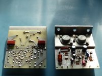
When I get my amps all back together I'll measure the voltage across R12, Wish I had ordered some 1 Watt resistors when ordering the other parts, I put the ceramic bead spacers on R12 when I very first built the amps as I guessed R12 was .5 watt for a reason. Way back then I don't think I ever paid any attention to actually how hot R12 gets, it was a case of, Switch on...... Nothing Blew up, Set Bias, connect Source and speakers ...... I have sound, Lid on, sit back and enjoy 🙂
Strange after 35 years plus, these little things are being noticed, and In some cases addressed.
Where is says R12, I mean R9 !! 😀
Looking good.
I think 12k isn’t the optimum value for R9 anyhow. More like 7k or 8k; best to measure the actual voltage across both of them before prescribing.
Obviously, power them up gingerly. 🙂
I think 12k isn’t the optimum value for R9 anyhow. More like 7k or 8k; best to measure the actual voltage across both of them before prescribing.
Obviously, power them up gingerly. 🙂
Thanks Mooly.Here you go:
It will be a little different on the real circuit; the base currents of TR3 & TR4 may vary and the power rails may be a little lower. But we can see the collector of TR3 is at a much lower voltage than TR4.
C4 is a mystery...why the rather specific value of 6.8nF?
R12?
- Home
- Amplifiers
- Solid State
- Any Maplin MosFet Amp Guru's on here?