Question:
Can't we generate the current for the LED digitally with a DAC? It would provide ultimate linear current output.
This is related to the fact I had a 12-bit Burr-Brown DAC80 that had discrete inputs ("12 complementary binary digital inputs") and an R2R current output. Now I gave them away (for experimentation to students) but we might find an alternative.
Such a dac could be encoded easily while the output will drive the LED current from anything like 1 micro amps to 4 milliamps in a totally linear way.
Would this be feasible? Needed?
I have not gone down to building yet
Can't we generate the current for the LED digitally with a DAC? It would provide ultimate linear current output.
This is related to the fact I had a 12-bit Burr-Brown DAC80 that had discrete inputs ("12 complementary binary digital inputs") and an R2R current output. Now I gave them away (for experimentation to students) but we might find an alternative.
Such a dac could be encoded easily while the output will drive the LED current from anything like 1 micro amps to 4 milliamps in a totally linear way.
- Stack some TDA1543's
- or make a current multiplier.
Would this be feasible? Needed?
I have not gone down to building yet
My 5 cents.
JP
Look nice! Just one build on this:
would it be beneficient if there was a voltage sense on the battery ; now I understand charging commences only once the external DC power supply is switched in (J1). The LiPo remains fragile for discharge . . .
Or double S1 to SPDT to connect J1 when turned off (shutdown is activated)?
My less than 2¢ thoughts
My 5 cents.
JP
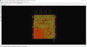
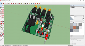
Is the cad model generated directly?
Sent from my iPhone using Tapatalk
At least one of our Members has already done this.Question:
Can't we generate the current for the LED digitally with a DAC? It would provide ultimate linear current output.
This is related to the fact I had a 12-bit Burr-Brown DAC80 that had discrete inputs ("12 complementary binary digital inputs") and an R2R current output. Now I gave them away (for experimentation to students) but we might find an alternative.
Such a dac could be encoded easily while the output will drive the LED current from anything like 1 micro amps to 4 milliamps in a totally linear way.
This way we should also be able to create the balanced output (for the top/bottom LED).
- Stack some TDA1543's
- or make a current multiplier.
Would this be feasible? Needed?
I have not gone down to building yet
And even better, it calibrates itself at first turn on.
It can be recalibrated later if one has reason to think the devices have gone off a bit.
The Voltage controlled current source lightspeed? I have that kit but never got around to assemble it. Perhaps I should find the time to do it.
Sent from my iPhone using Tapatalk
Sent from my iPhone using Tapatalk
Vincent's thread?
JP
Indeed. Arduino pwm outputs into mosfets. One of the best diy projects ever.
Last edited:
Indeed. Arduino pwm outputs into mosfets. One of the best diy projects ever.
Sounds great! Like to know more aboiut the kit.
I've built one recently. It absolutely sounds great. I want to thank George for sharing this smart design with DIY world. I warmly hope him joy, happiness and health on the rest of his life. Because it's such a classy behavior to give your own design which you put hard work into for free.
Sounds great! Like to know more aboiut the kit.
It's right up here, always close to the top of the list:
Arduino based LDR volume and source selection controller
Last edited:
I've built one recently. It absolutely sounds great. I want to thank George for sharing this smart design with DIY world. I warmly hope him joy, happiness and health on the rest of his life. Because it's such a classy behavior to give your own design which you put hard work into for free.
Aw-shucks😱😱
Cheers George
I'm still having a little sound eventhough I fully turned down the pot. What might be the problem?
I'm still having a little sound eventhough I fully turned down the pot. What might be the problem?
This is normal and louder if your "system gain" (source/poweramp/speakers) is high , as the led on the shunt ldr/s can't get it down to zero ohms as the max current for them to be reliable over the long term for these is 20mA.
Also if you leave it powered up when unused for a few days leave the volume at half, this way all 4 series and shunt ldr's only get 10mA each. Better practise to pull the power when not used.
Cheers George
What is the purpose of shunt ldr/s in the circuit? What do they provide?
The series and the shunt ldr's in the Lightspeed are working in opposing impedance's give the similar action to a normal 10kohm volume pot.
The shunt provides the attenuation to ground.
Cheers George
- Home
- Source & Line
- Analog Line Level
- Lightspeed Attenuator a new passive preamp