Has anyone ever made an attenuator using Cd S cells and LEDs instead of purchasing couplers?
Something like a GL5516 should work well and they reasonably cheap.
Something like a GL5516 should work well and they reasonably cheap.
My very first prototype was back in the 70's. For one channel CDS 2x cells from Nikon Light meters, in the ends of a tube about 3" long, in the middle a Led or could have been a neon lamp.
Cheers George
Cheers George
I ordered a hundred GL5516 and a hundred green-yellow LEDs. I'll see what I can come up with.
Maybe a new circuit.
Maybe a new circuit.
100k and 1V of Vdrop gives a current of 0.01mA.
Pass that through BOTH LEDs connected in series. Then measure the two LDR resistances.
You could use a 100k variable resistor in series and monitor the current with a 10k resistor where you measure Vdrop.
I went ahead with the build, skipping the measurements down to .01mA. I used the least matched pairs and sparing the best sets for the final ones. I'm happy to report that the built unit is performing well and producing amazing sound. The channels are balanced - I tuned by measuring the resistance of the LDRs and adjusting the trim pots with power on but no load.
I have to do further listening to give my final impression but so far what I am hearing from this attenuator is positive and consistent with some of the comments in the forum. I am so happy to have built my first, thanks to all your help.
I went ahead with the build, skipping the measurements down to .01mA.
For Diyer's 1mA to 20mA quad matching, with NSL32SR2S.
Down to 1mA is fine, unless you listen with the volume control at minimum, which is a whisper in most cases.
Unless you have a source with huge output an amp with <1v sensitivity, and 110db horns, then .1mA would be advised.
Now try powering with battery, as there is something about it that you can't put a finger on, even if you have noise free linear mains power.
Cheers George
George,
As soon I saw this, I replaced the temporary wallwart I'm using (its smp, though plugged to a power conditioner) with an ordinary 9V battery and WHOA! what an improvement. This thing is darn good!
It's more quiet, more clarity, the separation between instruments is much improved and the layering..wow. Instruments and vocals are convincingly realistic.
My plan was to replace the current wall wart with a low-noise linear regulated ps. It looks like using battery will be a better option. Now what to use??
Thanks so much. George.
An lm317 works well. Set to 5V or less.
A bit of smoothing before and some after is required.
Add on an electrolytic across the LED of the opto.
This helps hold the LED at constant current AND attenuates interference/noise at the LED.
A bit of smoothing before and some after is required.
Add on an electrolytic across the LED of the opto.
This helps hold the LED at constant current AND attenuates interference/noise at the LED.
An lm317 works well. Set to 5V or less.
A bit of smoothing before and some after is required.
Add on an electrolytic across the LED of the opto.
This helps hold the LED at constant current AND attenuates interference/noise at the LED.
I used the 7805 per original design by George, to set the 5V required. In addition to the caps already in the design, I also added an electrolytic and a ceramic cap across the LED side of the optos.
Fed from a 9V battery, the sound is much better than the switched wall wart I first used.
DV, if I were you I would consider Salas shunt regulator as an option 🙂
Selfy,
I checked the Salas SR thread here in diya, it's even longer than this thread, so it will take me sometime to read thru and decide. However, there was mention of Salas SSLV1.1 BIB boards guide (DocRev2) and PCB designed for 5V, which I'm trying locate. Is the PCB available for purchase? Is the input DC or AC that I still need a wall wart?
For LED drive, try a TL431 as a shunt regulator. You only need a few mA. Drive the top from a current source and you have a mini SSLV.
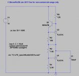
Something like this might be achievable with the elimination of the gang potentiometer and only using a single pot to control all four LED in the couplers.
R10 and 11 can be increased to set the minimum current through the LEDs, and thus the maximum resistance.
R16 is only there to measure total current to the network.
The disparity between C2,3,4,5 was to look at attenuation of ps noise vs cap value. Bigger is better, but too big a value results in a delay between adjusting the pot and the led current (and thus volume out) stabilizing.
Attachments
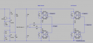
So, the trick is to match the components before assembling them into couplers.
Change R5 and R7 to a single pot and you can use it to adjust mismatch between channels.
Change R5 and R7 to a single pot and you can use it to adjust mismatch between channels.
Attachments
![DSCN2967[1].jpg](/community/data/attachments/553/553940-11fcb9a199f3c0fc033905668fd1ec44.jpg?hash=Efy5oZnzwP)
Last edited:
So, the trick is to match the components before assembling them into couplers.
Change R5 and R7 to a single pot and you can use it to adjust mismatch between channels.
You can make a Dual Mono (separate L&R volume controls), that way the matching isn't so critical.
Cheers George
Attachments
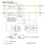
your signal should not be connected to the power ground.Something like this might be achievable with the elimination of the gang potentiometer and only using a single pot to control all four LED in the couplers.
R10 and 11 can be increased to set the minimum current through the LEDs, and thus the maximum resistance.
R16 is only there to measure total current to the network.
The disparity between C2,3,4,5 was to look at attenuation of ps noise vs cap value. Bigger is better, but too big a value results in a delay between adjusting the pot and the led current (and thus volume out) stabilizing.
See two posts later.
Georgehifi does not connect signal to power.
your signal should not be connected to the power ground.
See two posts later.
Georgehifi does not connect signal to power.
This is correct Andrew signal power - and + float.
But I just looked at my very first post and the 2nd diagram has a typo, and I can't change it.
The - (cathode) of all 4 of the led's should not go to chassis ground but to the - (negative) of the power supply. And the shunt ldr's go to chassis ground
Cheers George
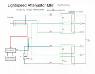
This is how it should look.
Attachments
Last edited:
- Home
- Source & Line
- Analog Line Level
- Lightspeed Attenuator a new passive preamp