Hello George,
Is there a method to match the LDR's? I got a lot of them from a friend and is looking to match them.
Best regards,
BP
Is there a method to match the LDR's? I got a lot of them from a friend and is looking to match them.
Best regards,
BP
Hello George,
Is there a method to match the LDR's? I got a lot of them from a friend and is looking to match them.
Best regards,
BP
Yes, very simple, it's in the first post.
Lightspeed Attenuator a new passive preamp
Cheers George
Hello George,
Thank you for the quick reply. I was able to find one on eBay. Going to purchase it so that I can give a try.
Do we need to match all the LDR's to the same value range or what is the matching criteria?
---
Best regards,
Binu Paul
Thank you for the quick reply. I was able to find one on eBay. Going to purchase it so that I can give a try.
Do we need to match all the LDR's to the same value range or what is the matching criteria?
---
Best regards,
Binu Paul
Last edited:
Hello George,
Thank you for the quick reply. I was able to find one on eBay. Going to purchase it so that I can give a try.
Do we need to match all the LDR's to the same value range or what is the matching criteria?
---
Best regards,
Binu Paul
To get a good progressive feel to the volume control, yes it is the best to quad match them.
Cheers George
Last edited:
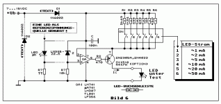
Yes this is the later model with even finer values, still cheap $12, for what's inside. Don't use the 35mA or 50mA you may blow the led.
KEMO M087N Light emiting diode-Tester LED Tester Made in Germany
Cheers George
KEMO M087N Light emiting diode-Tester LED Tester Made in Germany
Cheers George
Attachments
A stereo volume control needs at least 4 LED/LDRs.Hello George,
Thank you for the quick reply. I was able to find one on eBay. Going to purchase it so that I can give a try.
Do we need to match all the LDR's to the same value range or what is the matching criteria?
---
Best regards,
Binu Paul
if you can't get 4 that match to make a quad, then you should aim to get two sets of duals.
One dual matched pair are fitted to the series position of the L & R
The other dual matched pair are fitted to the shunt position of L & R
The series position shows very little effect if the LDR cannot go down to very low resistance when reaching the upper limit of ~20mA through the LED.
Conversely the shunt position requires the LDR to go down to low resistance when the LED current approaches 20mA.
For optimal volume control range I would put the low ohms LDRs into the shunt location and place the higher ohms LDRs into the series position.
Taking this a bit further:
use two low ohms LDRs in parallel in the shunt position on each channel. This can give an extra 6db in range than using a single.
Similarly use two higher ohms LDRs in series in the series position on each channel. This gives a further 6dB in range
The total increase in range using 8 LED/LDRs instead of 4 is ~12dB, i.e. from ~-50dB to -62dB
In all of these extra LDR arrangements the LED current passes through series combinations of LEDs
Last edited:
If I use 1M ohm dual pod instead of 100K, will I solve the problem which is I still hear the music sound although I fully turned down the volume pod?
Slightly. Do the numbers for LED current & LDR resistance when you insert 100k in the LED circuit and then change to 1M.
But you will also find that you increase the channel to channel imbalance when you go to extremes of LED currents.
Have you been able to measure the attenuation when turned to fully down?
If not then an alternative is to measure the LDR resistances when in the fully down rotation and then use these resistances to calculate/predict the attenuation and attenuation imbalance.
Have you measured your "normal attenuation" when you are listening at your normal/comfortable SPL?
Last edited:
Thank you Andrew. I understand what you mean and channel imbalance can be really an important drawback of using 1M. Nevertheless, I'll try it. Because a 9-10K attenuation may not be enough for especially high gain amplifiers and high output sources.
Hello George,
I have ordered the LED tester. Waiting for the item to arrive so that I can give it a try.
Best regards,
BP
I have ordered the LED tester. Waiting for the item to arrive so that I can give it a try.
Best regards,
BP
Yes this is the later model with even finer values, still cheap $12, for what's inside. Don't use the 35mA or 50mA you may blow the led.
KEMO M087N Light emiting diode-Tester LED Tester Made in Germany
Cheers George
I tried 1 Mohm voltage pod. Now lightspeed attenuator is behaving like 1.35-4.53 Mohm pod. Way too much for a passive amp.
George, what value of voltage pod should I try to get 20K or 30K out of lightspeed?
--
George, what value of voltage pod should I try to get 20K or 30K out of lightspeed?
--
If I use 1M ohm dual pod instead of 100K, will I solve the problem which is I still hear the music sound although I fully turned down the volume pod?
Last edited:
What is the resistance of the two 1Meg tracks when the knob is rotated halfway?
What is the LDR resistance when the LED is fed from that resistance?
What is the LDR resistance when the LED is fed from that resistance?
What is the resistance of the two 1Meg tracks when the knob is rotated halfway?
What is the LDR resistance when the LED is fed from that resistance?
Answer 1: 500K
Answer 2: 281K , 196K , 341K, 209K
500k for half rotation of a 1Mpot tells us you used a linear track pot.
You have been told to use a log law pot.
Using the wrong type of high value pot has resulted in an output impedance of approximately 130kohms.
You have been told to use a log law pot.
Using the wrong type of high value pot has resulted in an output impedance of approximately 130kohms.
Thanks for your inputs but not an answer to my question. To get a 20-50K output impedance according to my calculations 150 K pod will do the job, of course if I could find one ..😕🙄
500k for half rotation of a 1Mpot tells us you used a linear track pot.
You have been told to use a log law pot.
Using the wrong type of high value pot has resulted in an output impedance of approximately 130kohms.
if you want a maximum 20k for output impedance, then you need the two LDRs to have ~40k resistance when the series and shunt are at the same value.
You need to find what resistance in the LED feed circuit gives the LED current that gets to those 40k LDR resistances.
If you have you LED/LDRs to hand you can measure them to find that pot resistance value.
You need to find what resistance in the LED feed circuit gives the LED current that gets to those 40k LDR resistances.
If you have you LED/LDRs to hand you can measure them to find that pot resistance value.
When I look at the design I see one channel is controlling the current of both signal LEDs and the other is controlling both of shunt LEDs.
Is channel accuracy of dual pot a big deal for this design? Let's say we have a dual potentiometer with one channel is 110K and the other channel is 100K. Can you elaborate ..?
Is channel accuracy of dual pot a big deal for this design? Let's say we have a dual potentiometer with one channel is 110K and the other channel is 100K. Can you elaborate ..?
Last edited:
- Home
- Source & Line
- Analog Line Level
- Lightspeed Attenuator a new passive preamp