Not if it is Bi-fillar wound................ Think of the way the wire is wound on the bobbin - the length of wire used for a winding gets longer the further out it is. So the winding nearest the core is shorter than the one furthest away for the same number of turns.
The arithmetic seems screwy.
120 VA with four secondaries --> 30VA per secondary
Secondaries 1&2 in series ("center tap" config) --> 60VA for the combo
Secondaries 3&4 in series ("center tap" config) --> 60VA for the combo
First combo has 18+18=36V from end to end
60VA / 36V = 1.67 amperes max current
Ohm's Law: 1.67 amps x 54 ohms measured resistance = 90 volts dropped across the 54 ohms. Yet this is larger than the 36V open-circuit output voltage of the two secondaries in series.
I suspect that another measurement of the secondary resistances, will read far less than 54 ohms and 69 ohms.
Mark, sorry for confusion. 54R and 69R is not a resistance of secondary windings. It is Rs values in RC snubber that Quasimodo come up with. All math is correct up to V drop across secondaries. I can measure resistance and let you guys know.
It is 0.8R winding resistance on the side of 54R for Rs, and 0.9R on the side 69R of Rs. Same on both outputs.
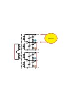
Four secondaries need four snubbers, even when some of the secondaries are connected in center tap configuration. See Figure 13 of Quasimodo design note.
If it were me, and if my Quasimodo showed that one 18V winding of a transformer was optimally snubbed with Rs=54 ohms, while another 18V winding of the very same transformer was optimally snubbed with Rs=69 ohms, then I would do this:
But that's just what I would do. You might prefer a different approach.
If it were me, and if my Quasimodo showed that one 18V winding of a transformer was optimally snubbed with Rs=54 ohms, while another 18V winding of the very same transformer was optimally snubbed with Rs=69 ohms, then I would do this:
I'd find the geometric mean of 54 and 69 (answer: 61), and I'd try Rs=61 on each of the secondaries. I'd look at the resulting oscilloscope waveforms and ask myself: Can I live with these? If the answer was yes, then I'd use Rs=61 ohms for both and I'd be happy. If the answer was no, then I'd open the Quasimodo design note in Acrobat Reader and search for the word "skeptical". I'd read the paragraphs containing that word and then look deep into my soul.
But that's just what I would do. You might prefer a different approach.
Did you short 3 secondaries during measuring one?Mark, sorry for confusion. 54R and 69R is not a resistance of secondary windings. It is Rs values in RC snubber that Quasimodo come up with. All math is correct up to V drop across secondaries. I can measure resistance and let you guys know.
Did you short 3 secondaries during measuring one?
Page 11, last image in manual. In addition, I shorted second 3 wires set of secondary winding.
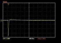
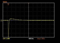
After a few months sitting on the back burner I finally got to repairing my Quasimodo. During my original build I had fired it up with the NTD4906 in backwards and let the smoke out of the MPC1407. I decided to replace the NTD4906, MPC1407, and LMC555. Finding the NTD4906 proved to be difficult. I ordered some from a company called PEAWO. What I actually received were NTD4969, but since I had them I thought I would give them a try. They seem to work just fine. Attachments are Ceapomodo (left) and Quasimodo (right) with the exact same Cx, Cs, and Rs.
Attachments
The Bill Of Materials (contained in the .zip archive attached to post #1) lists two other recommended MOSFETs, and the "FAQ" in post #1 tells you where to obtain information about MOSFET selection.
Adjusting the scope and power supply settings exactly the same as figure 3 in the Quasimodo paper produces different results for me. Why is that? Only after adjusting the time to 500ns do I get a somewhat similar trace.


Period of oscillation is proportional to sqrt( (Cx + Crectifiers) * L_leakage) as shown in Quasimodo equation (C.2).
If the actual capacitance value (perhaps not the marked value!) of your Cx is different than the actual capacitance value of Cx used in Figure 3, then your oscillation period will be different than the oscillation period in Figure 3.
If the leakage inductance of the transformer secondary you're measuring, is different than the leakage inductance of the transformer secondary measured in Figure 3, then your oscillation period will be different than the oscillation period in Figure 3.
If we use the symbol "Lbig" to denote the biggest leakage inductance of a transformer secondary measured by any of the 150+ Quasimodo users all around the world,
And if we use the symbol "Lsmall" to denote the smallest leakage inductance of a transformer secondary, measured by any Quasimodo user all around the world,
Then I would not be surprised to learn that the ratio (Lbig / Lsmall) was more than ten thousand. I will let you figure out how to plug that assumption into equation (C.2) and draw a conclusion about oscillation periods.
Hi Mark,
In the RC snubber section of the PDF, you mention:
However, the test jig doesn't include the rectifiers. So wouldn't you want the injection capacitor Cx = C2 to be approximately the same as your CRECTIFIER, rather than vanishingly small?
Thanks,
Jeff.
In the RC snubber section of the PDF, you mention:
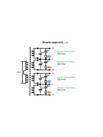
One approach is to select a very small injection capacitor Cx = C2 in Quasimodo. Because Cx increases the total capacitance (CT + Cx + CRECTIFIER) across the secondary, an RC snubber wants Cx to be negligibly small compared to (CT + CRECTIFIER). If it is, the error introduced by having a tiny Cx present in Quasimodo testing, but absent from the final product design, is very small.
However, the test jig doesn't include the rectifiers. So wouldn't you want the injection capacitor Cx = C2 to be approximately the same as your CRECTIFIER, rather than vanishingly small?
Thanks,
Jeff.
Yes that's right, sorry for the confusing wording on page 13 "The two element, RC snubber (non preferred)".
The audio equipment has a transformer and rectifiers but no Cx
The Quasimodo test setup has a transformer and Cx but no rectifiers.
To make them operate identically, we want Cx_in_Quasimodo == Crectifier_in_audio_equipment. Just as you said.
However, I myself find the two component "RC" snubber to be inferior to the three component "CRC" snubber.
Thanks, Mark.
Yeah, most of my snubbers will be CRC. There's just one for a tube B+ circuit that I'm having room issues (tube-voltage caps being non-trivial in size).
Cheers,
Jeff.
Yeah, most of my snubbers will be CRC. There's just one for a tube B+ circuit that I'm having room issues (tube-voltage caps being non-trivial in size).
Cheers,
Jeff.
Hmmm... I did find a SMC C0G that will fit. It's not a film, but I assume a C0G Cx is better than no Cx at all?
I like film capacitors because they have very low dissipation factor ( tan δ ). If you can find a C0G ceramic capacitor with low tan δ then I think you will be happy.
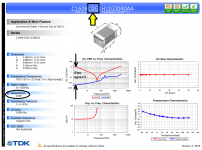
An example from TDK (found on DigiKey's website) is below. This capacitor's self resonance (where Z dips dramatically) is about 50 MHz. At a frequency about two decades lower, the ESR more than 3 orders of magnitude below the Z. So this capacitor's tan δ is quite low at 1 MHz and below. Acceptably low, I would imagine.
But the nice thing about Quasimodo is: you can actually see the result of your component choices. You can actually see the waveform's shape. If you look at the "before" (Rs=Infinity) waveform, and then the "after" (Rs=optimum=Zeta_1p0) waveform, and if you decide that you like the "after" waveform, then you're done. To heck with dissipation factor, to heck with film vs ceramic, to heck with it all. If you like what you see, then you're done.
_
Attachments
I checked the C0G's I had in mind (KEMET), and was somewhat surprised to find they have a DF of 0.1%; same as the films I was looking at (Wima MKS2).
I can get the SMD C0Gs much closer to the transformer pins, so that has to be a win as well....
Cheers,
Jeff.
I can get the SMD C0Gs much closer to the transformer pins, so that has to be a win as well....
Cheers,
Jeff.
- Home
- Amplifiers
- Power Supplies
- Simple, no-math transformer snubber using Quasimodo test-jig