Mark,
thanks for the link. My daughter was asking for a project to do. This should work well with her Digilent Explorer breadboard and scope. I have a few transformers lying about she can play with.
thanks for the link. My daughter was asking for a project to do. This should work well with her Digilent Explorer breadboard and scope. I have a few transformers lying about she can play with.
It is a lot of money. It is a LOT of money. Don't even think of buying, without consulting your shaman, your life coach, your horoscope, your crystalline aura, and your personalized Google Fraud Detection Algorithm. Don't let anybody pressure you into paying a huge amount, until you have done your own research (your own self) and achieve your own peace of mind. YOU control the money and YOU control the timeline. The "worst" that can happen is, that someone else buys what you leisurely decided to bid for. But how is this "bad"? What injury has been done to you? You still have your skull, you still have your pride, you still have your money; who cares what somebody else has (or has not) purchased?
In many arenas outside the home team players locker room there is a Coca-Cola machine that dispenses cans for $.25 as there is considerable corporate desire for folks to see the players with a can in their hand.
In one arena it was $.50. As the circus was in the arena I saw one of their foreigner contract performers folks slam his hand on the machine and exclaim "What a ripoff in the last arena it was a quarter!"
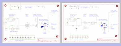
Wow those first two schematics posted in #1202 are small. I asked MS Paint to blow them up by 5X, just so I would have an easier time drawing on them.
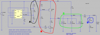
In my opinion there are four differences, labeled with the letters A , B , C , and D in the pictures below. You might want to go back to the original full-size schematics to study these further.
The last one ("D") is different because the surface mount Quasimodo ("v.3") uses a fixed, soldered-down, unchangeable 0.15uF capacitor in this position. The other two boards ("v.4" , "CheapoModo") have a socket in this position, allowing users to swap in different capacitors here, if they so desire.
The other three are self evident from studying the schematics.
_
Attachments


Mark
Sorry about the image size, I grabbed them from your #1 post from your thread and just copied and pasted. Thank you for the redlines, I'll study the differences now that I know what they are. I think you said earlier that you did a breadboard version with perf-board and thru hole parts and all was well. So there is no practical reason to go with the smd version of the build?
Sorry about the image size, I grabbed them from your #1 post from your thread and just copied and pasted. Thank you for the redlines, I'll study the differences now that I know what they are. I think you said earlier that you did a breadboard version with perf-board and thru hole parts and all was well. So there is no practical reason to go with the smd version of the build?
diyAudio member requests advice, suggestions: Help !!
Would anyone like to offer any advice to a diyAudio member who is experiencing difficulties with her/his SMD Quasimodo v.3 ?
Would anyone like to offer any advice to a diyAudio member who is experiencing difficulties with her/his SMD Quasimodo v.3 ?
I'm out of ideas about what I'm doing wrong with my Quasimodo v.3. Can't get a desired view on scope. It might be my SMD circuit is not working as needed and it is hard to troubleshoot it due to its size. Can you please help me to figure out? It might be also related to my lack of scope use knowledge and I do not have any friend who can show me "how".
I connected CH1 and CH2 as advised to the board and set AC coupling for both.
Trigger is set to Edge and Falling Down direction on CH1. V/dev is set to 10v for CH1 and 5v for CH2. I played with Time/dev and do see some weird waveforms. I supply 15VDC to that board. Tried several transformers... I start with no trimmer. Do I miss anything?
Would anyone like to offer any advice to a diyAudio member who is experiencing difficulties with her/his SMD Quasimodo v.3 ?
I just ran into some similar problems building a V4 board because I didn't pay attention to how I connected the transformer
 (single primary, dual secondaries) so be sure it is connected exactly as Mark shows in his tutorial.
Before hooking up the transformer though, check the board over with a scope: Remove C2 (0.01uF cap) and check for the square wave on pins 5-8 of mosfet where they connect to R1 (4.7K Res) - the "input" side of C2. You should see something close to 120 Hz square wave there. I measured 120 Hz on one V4 board and 114 Hz on other. If it's there, then your problem is after C2. If it's not there, check backwards through the schematic.
If this doesn't help, a picture or schematic of your set-up would be useful.
Phil
Would anyone like to offer any advice to a diyAudio member who is experiencing difficulties with her/his SMD Quasimodo v.3 ?
Are you using a 'scope with a CRT? On my Tek 2445, it is nearly impossible to see the trace in a well-lit room.
Hi Phil,
Thanks for your tip. I'll test it as you directed and update today at night. Hope it will bring some clarification about what is going on with my board.
Thanks for your tip. I'll test it as you directed and update today at night. Hope it will bring some clarification about what is going on with my board.
You bet, Alex. I've got some more transformers to test so I can follow along with a V4 board if it comes to that.
Are you using a 'scope with a CRT? On my Tek 2445, it is nearly impossible to see the trace in a well-lit room.
I tried both. I have an old analog Tek and I went to max brightness in order to see trace. Played with focus a bit and it worked out fine. I also have dig cracked for 100MHz Rigol 1052. I do not think it is a scope issue. Most likely it is something wrong in my SMD board.
Mark, PH104 and GOR3 - thank you all guys for such quick and excellent support. I found the issue and fixed it already. All works perfectly fine now.
So, I did not get a square wave on PIn 8-Vdd and Pin 5-GND. Then, I inspected all devices located prior that point with my microscope that I use for SRA tonearm setup. I fond that SMD MOSFET got a lifting on one side and all 4 legs are in air. Re-soldered it back and measured 119.5 Hz at that point with perfect shape of square wave. All work like champ now. Measured several transformers and it is very easy to see Rs values. Thank you a lot.

So, I did not get a square wave on PIn 8-Vdd and Pin 5-GND. Then, I inspected all devices located prior that point with my microscope that I use for SRA tonearm setup. I fond that SMD MOSFET got a lifting on one side and all 4 legs are in air. Re-soldered it back and measured 119.5 Hz at that point with perfect shape of square wave. All work like champ now. Measured several transformers and it is very easy to see Rs values. Thank you a lot.

That's why the PCB for v.4 is twice as big as the PCB for v.3; the extra space is consumed by (among other things) a DIP switch and some option resistors. These let you speed up Quasimodo's oscillator, increasing the duty cycle ratio of the CRT beam and brightening the displayed trace.Are you using a 'scope with a CRT? On my Tek 2445, it is nearly impossible to see the trace in a well-lit room.
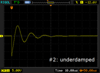
Have a look at a typical Quasimodo lab experiment, such as the one attached below. If this were an analog scope, its CRT beam would be ON for (12 div * 10usec/div) = 120usec. The beam would be OFF for the remainder of the oscillator's period (8300usec). So the duty cycle of the electron beam painting the screen, is 120/8300 = 1.4% . No wonder it's dim!
v.4 allows you to speed up the oscillator by 5X or by 25X, increasing the duty cycle and brightening the trace by that same factor of 5 or 25.
Of course this is unnecessary for digital storage oscilloscopes that paint the LCD screen from a bitmap stored in RAM. But folks using analog scopes might want to monkey around with the DIPswitches on their v.4 PCB.
_
Attachments
... I fond that SMD MOSFET got a lifting on one side and all 4 legs are in air. Re-soldered it back and ... All work like champ now.
Congratulations!
I find that when I hand-solder an SMD board, the vast majority of the failures I get are open circuits (rather than short circuits). For some reason, the mistakes I make when soldering and inspecting surface mount boards, always result in "Component pin not electrically connected to PCB pad". This is sometimes cumbersome to diagnose with an ohmmeter / continuity buzzer. Argh.
Hi Mark
My V3 are assembled and work GREAT. I only have one comment, that is the PCB should be wider as I like to add standoffs to mount my projects.
Again great work.
Duke
My V3 are assembled and work GREAT. I only have one comment, that is the PCB should be wider as I like to add standoffs to mount my projects.
Again great work.
Duke
Duke, check with the author of post #1212. The photo attached there, seems to show standoffs.
Mark is right. I do use standoffs and my Quasimodo is boxed together with Marks trany polarity tester. I took them out just for Quasimodo fixing. 


For guys who got measured transformers with center tap. Have 120VA R-Core with 4x 0-18v outs. Set it up for 2 outs of 18-0-18. Now is my question: 1st set of 18-0 measured 54r on both outs and other sets 0-18 measured 69r. Is it common case to have such imbalance for Rs?
- Home
- Amplifiers
- Power Supplies
- Simple, no-math transformer snubber using Quasimodo test-jig