Feedback... yes, but more positive than negative, on demand said Bob Cordell.Forr, I feel for you. I have been in a similar situation. Years ago, when I discovered error correction à la Hawksford, I was convinced it was a novel method for designing amplifiers. Several here tried to help me see that it was just standard feedback in another cloak.
Your PAX amplifier is a very interesting piece to study and analyse.
.
Last edited:
Your PAX amplifier is a very interesting piece to study and analyse.
.
Second that. Been simulating this over the past week or so. I like the fact that you can combine either the LT1166 or Pioneers PA0016 for autobias with this HEC implementation.
Also, learnt that the AD844 is a very useful op amp that I don't mind using instead of discrete parts.
Paul
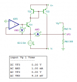
Referencing to post #447 ( Current Feedback Amplifiers, not only a semantic problem ? ) we see that the inverting input at emitter of T1 does not constitute a very good virtual earth :
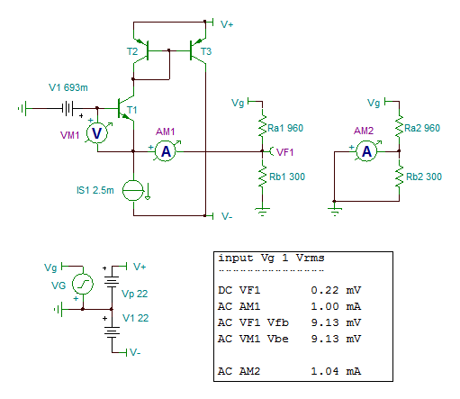
However (in simulation and at low frequencies) this can obtained by using a local feedback using an op-amp to drive T1 which becomes T31 in the next schematic :

Inverting input AC voltage VF3 is now 0V, it's an ideal earth input.
Ra has been slightly modified to get an emitter AC current of 1 mA for T1.
The AC load of T1 emitter is Ra3, passing a current modulated by Vg.
AC voltage of T1 Vbe controls the required AC current to this load. Its value VF3 at 9.18 mV is very similar to V1 at 9.13 mV in the first schematics.
It occurs to me that considering the Vbe voltage to deliver the required current to the emitter load of V1 is, in all cases, the best way to correctly analyze this kind of input stage having a low impedance inverting input.
.
However (in simulation and at low frequencies) this can obtained by using a local feedback using an op-amp to drive T1 which becomes T31 in the next schematic :
Inverting input AC voltage VF3 is now 0V, it's an ideal earth input.
Ra has been slightly modified to get an emitter AC current of 1 mA for T1.
The AC load of T1 emitter is Ra3, passing a current modulated by Vg.
AC voltage of T1 Vbe controls the required AC current to this load. Its value VF3 at 9.18 mV is very similar to V1 at 9.13 mV in the first schematics.
It occurs to me that considering the Vbe voltage to deliver the required current to the emitter load of V1 is, in all cases, the best way to correctly analyze this kind of input stage having a low impedance inverting input.
.
Attachments
Last edited:
Second that. Been simulating this over the past week or so. I like the fact that you can combine either the LT1166 or Pioneers PA0016 for autobias with this HEC implementation.
Also, learnt that the AD844 is a very useful op amp that I don't mind using instead of discrete parts.
Paul
I once had the opportunity to ask a person very highly placed at ADI about an improved AD844-like CCII. He told me that 'we have a much improved design ready, but no sales prospects - nobody would buy it'.
He also told me, 'if we wouldn't call the AD844 an opamp, nobody would buy it either'. In some respects, the IC opamp market shows also signs of a fashion market.
Jan
Shame we can't find out how it has been improved. Had a discrete version planed with Hawksford cascodes at the current conveyor output along with miller compensation. This improved the THD close to clipping.
Now since learning the AD844 is effectively the same thing, my design is now back in flux thanks to studying your PAX amplifier. 😉 Especially like the HEC VAS.
Doesn't surprise me that the IC op amp market resembles a fashion market - wherever you find marketing this appears ineviteable.
Paul
Historically, as I pointed out, the current mode amplifier has been around for a long time. With some applications type engineers there was confusion and then the buffer added to the normally low Z port helped make it seem like a fast VFB amp. And learning how it worked inside was side-lined. Just pretend it is the same old VFA they were used to using. But if DIY'ers want to make one with descrete transistors, we have to know how they work inside...........
carry on......back to what it is and how it works. I think we did this a few years ago on another forum/thread....... maybe others could find it and read it. Some really good amplifiers were designed as well.
View attachment 631956
I am interested in newer designs... like those using cmos and some parts of it maybe used for audio.... progression and evolving..... moving on....
THx-RNMarsh
I showed in other CFA thread schematic with complementary jfets input. It is a bit simpler, but very hard to find suitable complementary jfets and those released recently from Linear Systems are quite expensive, 12$ for one if you buy two complementary pairs.
I decided to go BJT route.
Attachments
Shame we can't find out how it has been improved. Had a discrete version planed with Hawksford cascodes at the current conveyor output along with miller compensation. This improved the THD close to clipping.
Now since learning the AD844 is effectively the same thing, my design is now back in flux thanks to studying your PAX amplifier. 😉 Especially like the HEC VAS.
Doesn't surprise me that the IC op amp market resembles a fashion market - wherever you find marketing this appears ineviteable.
Paul
I do have a much improved version, but need to find the time to elevate it to project status ;-)
Jan
Some really good amplifiers were designed as well.
progression and evolving..... moving on....
Interesting, the output servo in the second picture was already being used in .1-10Hz noise test boxes when I started in 1973. The input coupling caps were too leaky at the very low corners. No idea who built them maybe Dick Burwen?
DA tests with asymmetrical waveforms -- pulses etc show the added 2H (via FFT) where as sine waves always average to zero. I only guessed that this was what people were hearing because when DA was minimized they reported better resolution. Asym --no average to zero componenet -- was used to see f there was anything to show different from sine waves. I had a hunch.
You must be taking repetition lessons from JC.
All AC coupled waveforms average to 0. A symmetric waveform has odd harmonics based on the non-linearity of the transfer function and the math to extract it are high school algebra and the harmonics for any input can then be calculated. The voltage coefficient of capacitance and DA are not the same thing (they certainly can both exist together). But pure DA can not make harmonics for any input stimulus.
I once had the opportunity to ask a person very highly placed at ADI about an improved AD844-like CCII. He told me that 'we have a much improved design ready, but no sales prospects - nobody would buy it'.
But the AD846 did happen and yes no one bought it.
You must be taking repetition lessons from JC.
All AC coupled waveforms average to 0. A symmetric waveform has odd harmonics based on the non-linearity of the transfer function and the math to extract it are high school algebra and the harmonics for any input can then be calculated. The voltage coefficient of capacitance and DA are not the same thing (they certainly can both exist together). But pure DA can not make harmonics for any input stimulus.
All true.... but not completely true. Depends on the test method what you will see/get for result. Voltage coeeff seems rather small also in film caps.... but if a test showed it also follows the DA in audible ranking, then maybe it or both are suspect for hi-end apps.
BTW - I didn't use ac coupled waveforms in my DA test setup. And low Z vs high Z circuit/time constant has a major affect on the DA results. Low Z circuits being better. It was a correlation with listening (others) that matched DA to sonic results. weak argument ? maybe. maybe not.
THx-RNMarsh
Last edited:
Error correction was encouraged over only using feedback as a means to reduce distortion and we got a spate of them for awhile. Some, especially OPS error correction is simple enough and fool proof enough that it should be in all high end amplifiers. In which case, I would think for all practical purposes would make them nearly 'perfect' (<-100dB thd/pwr/freq/Z).
From the Spectacular results in distortion reduction, this seems the best route to take.... rather than CFB and/or VFB alone. Esp in power amps.
IMV
THx-RNMarsh
From the Spectacular results in distortion reduction, this seems the best route to take.... rather than CFB and/or VFB alone. Esp in power amps.
IMV
THx-RNMarsh
Last edited:
Do any of the error correction schemes affect the PA output Z in any way?
THx-RNMarsh
THx-RNMarsh
Last edited:
It occurs to me that considering the Vbe voltage to deliver the required current to the emitter load of V1 is, in all cases, the best way to correctly analyze this kind of input stage having a low impedance inverting input.
.
Ironically forr your last diagram illustrates the point perfectly. As an op-amp the inverting input stays the emitter of T1 while the non-inverting input becomes the + input of IOP3. Now say there is a distortion mechanism internal to the whole amplifier, well there is identically zero volts across the + to - input so the error appears totally as the voltage caused by the CURRENT through Ra1 into the - input. Notice further that the voltage across Rb1 follows the input exactly so all errors are referred to output via Ra1 independent of closed loop gain. This includes noise current and any displacement current in the compensation capacitor.
The diamond transistor arrangement is simply an imperfect current conveyor, the addition of the op-amp makes it almost perfect. The GBW is still determined by the feedback network and now obeys the CFA behavior even more. Yes this arrangement can have some compensation issues but that has nothing to do with the fundamental operation. I have built these with IC's BTW and they can work.
Do any of the error correction schemes affect the PA output Z in any way?
THx-RNMarsh
If they're error correcting then obviously they must be *attempting* to minimize output Z. Obviously you'll have parts of the output impedance that are out of the feedback/corrective loops, so they'll be unaffected.
The AD846? Looks like a WONDERFUL OP AMP! Have any samples left Scott? It is fast, low differential phase, low noise (when carefully used), etc, etc. Too bad it was discontinued, it would have made a wonderful (compared to most others) OP AMP for quality audio.
Except in my stash 😀
I don't think it is that different from the '844, except for the max Iout from the CC.
Jan
I don't think it is that different from the '844, except for the max Iout from the CC.
Jan
What a shame! Finally AD makes a part that we (hi end audio designers) can really use, and they discontinue it! '-(
I do have a much improved version, but need to find the time to elevate it to project status ;-)
Jan
Hopefully one day you'll make it public 🙂
I have my own version in my mind. Like you need time to develop it. At least make an LTSpice simulation up. Already given away that it will have autobias of some sort.
Life just takes up too much time....
Paul
- Home
- Amplifiers
- Solid State
- Current Feedback Amplifiers, not only a semantic problem?