In a similar vain, after Walt and I published articles on capacitors used in audio of the era and esp dielectric absorption issues in many designs..... I was talking to Walt Jung and suggested to him that the best cap was no cap. he asked what about drift and offset issues... esp in a high gain phono stage? I had been reading about mechanical servo systems and suggested he use a servo. being a clever person he talked with his peers and came up with an opamp servo for his preamp. The first to publish such concept. AFTER that article came a mathematical treatment by another person of all the opamp configurations an engineer could us an opamp as servo.
Ideas, concepts and problem solving comes in all forms -- for me, it is from a systems view and broad back ground (master of nothing back ground). Solutions do not all come from the universities and ivory towers nor mathematicians... ask Einstein. Often a solution to a problem or question comes first from a necessity.
THx-RNMarsh
Last edited:
The RTA concept was another out growth of necessity......
I had started doing room response measurements with single freqs and a mic and plotting the results. Then a swept gen helped and then a noise gen and a pink noise gen and mic with octave filters and measuring the spl levels and plotting them. very time consuming... why turn this filter dial? use a bunch of filters and automatically select them..... if done fast enough, I can display it on my scope screen. Eventually a bunch of 1/2 octave filters with 741 opamps were put in parallel, rectified and smoothed and sequentially selected with a 555 timer and timing gate chip... added a log converter chip and output to scope for the RTA. The concept was given to another engineer who did the design and pcb and we published the circuitry as a DIY article. Within a year the Japanese had it all in 2 chips. and an light/ led display. Later, I bought the very first MLSSA from DRA for my lunch box PC and never looked back.
I would suggest to Waly that instead of taking ideas that have survived the test of time., and dissecting into minute details in SIM et al.... come up with improvements or even some brand new ideas of his own to contribute.
All my audio contributions ... occurred when I was in my 30's. After that, contributions where not in audio. It was only later in life... 60-ish did I get back to audio with power line noise issues and new products there as well.
Lead instead of following, Waly.
THx-RNMarsh
Last edited:
It is not global feedback, the loop is broken.
The circuit can play the role of a non-feedback virtual earth.
Approximately.
Come on forr. This is a standard and well accepted analysis technique - see Middleton
Quote:
Originally Posted by Waly
I find it funny people claiming having me on their ignore list, but still going through the trouble of replying to my posts
Unfortunately, your comments come up when others quote you.
However, I should be man enough to just ignore them. Ill give you that.
Originally Posted by Waly
I find it funny people claiming having me on their ignore list, but still going through the trouble of replying to my posts
Unfortunately, your comments come up when others quote you.
However, I should be man enough to just ignore them. Ill give you that.
--- hey Waly... I just read something that reminded me a lot of you ----
If I give you A STRAW,
WILL YOU suck the fun out of someone's ELSE'S DAY?
---
[If you don't drink,,...... how will your friends know that
you love them at 2am?]
-RM
If I give you A STRAW,
WILL YOU suck the fun out of someone's ELSE'S DAY?
---
[If you don't drink,,...... how will your friends know that
you love them at 2am?]
-RM
Last edited:
Here, inspired by figure 3 of S. Franco's article,
In defense of the current-feedback amplifier | EDN
here is a simplified CFA input stage with the injection of a current at the inverting input (emitter of T1) which has been set to 0 DC by V1.
Ra1 was adjusted so as to obtain an AC current of 1 mA entering the inverting input. The quiscent current of T1 is 2.5 mA, defined by constant current source IS1. This leads T1 to present an impedance of about 10 Ohm on its emitter and a transconductance of 100 mA/V
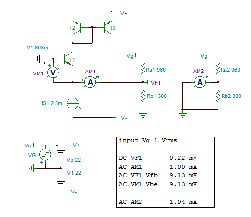
As the non-inverting input is connected to ground, the inverting input is expected to behave like a virtual earth, without presenting any AC voltage. Ideally current sensed by AM1 should be equal to current sensed by AM2, voltage across Rb2 being null. Here these currents are respectively 1.00 and 1.04 mA.
AC voltage at VF1 is equal to the Vbe of T1, and is 9.13 mV. It is in good accordance with the AC current of 1 mA sensed by AM1 and the transconductance of T1 of 100 mA/V.
Conclusion : the correlation between the input stage AC current (Ie of T1) and the AC voltage accross the inputs (Vbe of T1) is high.
This is in serious contradiction with the notion of current feedback.
.
In defense of the current-feedback amplifier | EDN
here is a simplified CFA input stage with the injection of a current at the inverting input (emitter of T1) which has been set to 0 DC by V1.
Ra1 was adjusted so as to obtain an AC current of 1 mA entering the inverting input. The quiscent current of T1 is 2.5 mA, defined by constant current source IS1. This leads T1 to present an impedance of about 10 Ohm on its emitter and a transconductance of 100 mA/V
As the non-inverting input is connected to ground, the inverting input is expected to behave like a virtual earth, without presenting any AC voltage. Ideally current sensed by AM1 should be equal to current sensed by AM2, voltage across Rb2 being null. Here these currents are respectively 1.00 and 1.04 mA.
AC voltage at VF1 is equal to the Vbe of T1, and is 9.13 mV. It is in good accordance with the AC current of 1 mA sensed by AM1 and the transconductance of T1 of 100 mA/V.
Conclusion : the correlation between the input stage AC current (Ie of T1) and the AC voltage accross the inputs (Vbe of T1) is high.
This is in serious contradiction with the notion of current feedback.
.
Attachments
Hint: think of local feedback in the 1'st stage through feedback resistors beyond "ideal" operations, i.e. when OL gain decreases and phase shift increases with frequency. ;-)
In a similar vain, after Walt and I published articles on capacitors used in audio of the era and esp dielectric absorption issues in many designs.....
Mostly not relevant to a skilled designer. My inputs were ignored as inconvenient truth, the Pease model of DA is linear and only causes trivial frequency response deviations. High K ceramics are an easy strawman, gee look folks capacitors can distort.
WTF Waly in the bin and this stupid thread keeps on rolling.
Mostly not relevant to a skilled designer. My inputs were ignored as inconvenient truth, the Pease model of DA is linear and only causes trivial frequency response deviations.
Did anybody educated have any doubts? Unless, non-linearity has nothing to do with absorption itself, but presents in the same device.
Linear DA does give nonlinearities in S/H, integrating/slope conversion ADC
so that may have been a source for the assumption
but Linear DA in Linear Filters, Audio doesn't give rise to nonlinearities - rather milli or micro dB low bass frequency response variations from an ideal cap
so that may have been a source for the assumption
but Linear DA in Linear Filters, Audio doesn't give rise to nonlinearities - rather milli or micro dB low bass frequency response variations from an ideal cap
Linear DA does give nonlinearities in S/H, integrating/slope conversion ADC
If you remember that was the whole point of the Pease article, compensating for DA in integrating A/D's. This does not translate into non-linearity in continuous time analog uses. To be sure they can both occur in some capacitor technologies but the articles use more of a "scare tactic" approach rather than a serious attempt at teaching engineering around problems. The claims of audibility are weak and based on the usual uncontrolled or otherwise biased listening tests.
Last edited:
Linear DA does give nonlinearities in S/H, integrating/slope conversion ADC
It is completely different story!
For S/H in an analog music synthesizer I used Teflon FT-4 caps; it was the only case when I used them, besides in S/H of a lacquer impregnation quality measurement instrument.
Some have conveniently forgotten the context of thee capacitor article with W.Jung....... in the 1960-70's the coupling capacitor of choice was (and often still is) the electrolytic capacitor. For tube circuits it was a film (mylar).
The idea was to determine why in ss circuits, replacing the electro with a film was audible. There were several mechanisms of those polar caps and apps which increased distortion. Including their DA... especially evident in high Z areas. Films measured a lot better and when electro was replaced with film and speaker bi-polar types with films.... there was an audible improvement in recovered details heard around the world. It was also demonstrated that the DA of a cap had a direct correlation to those audible results in subjective ranking.
DA tests with asymmetrical waveforms -- pulses etc show the added 2H (via FFT) where as sine waves always average to zero. I only guessed that this was what people were hearing because when DA was minimized they reported better resolution. Asym --no average to zero componenet -- was used to see f there was anything to show different from sine waves. I had a hunch.
The biggest problem that followed was claims of hearing the differences between different construction and DA of various film types. Differences of large DA of electro vs film was easy. but film to film? A lot harder... though others seem to hear differences, I never tried to listen for such differences.
Just a little back ground......
THx-RNMarsh
Last edited:
W.Jung (?) IIRC also did a mod on a CD player where the dac used a lot of high DA caps ... he replaced them with low DA types and reported (as did others who did the mod) that there was an improvement in detail/resolution.
Then bypassing was applied with better caps etc -- all places where the better films could be used and in most cases there was an improvement.
Now we just use the better and lower DA part as a matter of course ... like we now do with better resistors (mf etc). Or for coupling we move to no coupling cap at all via dc servo and direct-coupled topologies.
progression.... evolving.
THx-RNMarsh
Last edited:
Gentlemen, is the initial subject of this thread so disturbing that you need to divert the discussion ?
Historically, as I pointed out, the current mode amplifier has been around for a long time. With some applications type engineers there was confusion and then the buffer added to the normally low Z port helped make it seem like a fast VFB amp. And learning how it worked inside was side-lined. Just pretend it is the same old VFA they were used to using. But if DIY'ers want to make one with descrete transistors, we have to know how they work inside...........
carry on......back to what it is and how it works. I think we did this a few years ago on another forum/thread....... maybe others could find it and read it. Some really good amplifiers were designed as well.

I am interested in newer designs... like those using cmos and some parts of it maybe used for audio.... progression and evolving..... moving on....
THx-RNMarsh
carry on......back to what it is and how it works. I think we did this a few years ago on another forum/thread....... maybe others could find it and read it. Some really good amplifiers were designed as well.
I am interested in newer designs... like those using cmos and some parts of it maybe used for audio.... progression and evolving..... moving on....
THx-RNMarsh
Attachments
Last edited:
Gentlemen, is the initial subject of this thread so disturbing that you need to divert the discussion ?
Forr, I feel for you. I have been in a similar situation. Years ago, when I discovered error correction à la Hawksford, I was convinced it was a novel method for designing amplifiers. Several here tried to help me see that it was just standard feedback in another cloak.
But I was so blinded by my own correctness that I didn't see it. Discussions sometimes became a bit ugly, and I was grabbing at all kinds of arguments that - in my limited view - would prove I was right. Looking back to that episode I still hardly understand why I didn't see it, because 'they' were right. Only many months later, when I had distanced myself and calmed down, did I get my Eureka! moment.
It was a sobering episode, but I learned a lot. Mostly about myself 😉
Jan
- Home
- Amplifiers
- Solid State
- Current Feedback Amplifiers, not only a semantic problem?