instead of VFets , solder 1K8 resistors
resistor between D and S of VFet
plain MF 600mW resistor will do
be sure that FB net is enclosed
power on, set both VFet bias voltages to max and same voltage (P1 and P2 , voltage say + and - 12V) at gates of VFets
now check all interesting nodes
power off ,desolder 1K8 resistors, mount VFets (check torque , check isolation to heatsink) , power on and set Iq and offset
Last edited:

instead of VFets , solder 1K8 resistors
resistor between D and S of VFet
plain MF 600mW resistor will do
be sure that FB net is enclosed
power on, set both VFet bias voltages to max and same voltage (P1 and P2 , voltage say + and - 12V) at gates of VFets
now check all interesting nodes
power off ,desolder 1K8 resistors, mount VFets (check torque , check isolation to heatsink) , power on and set Iq and offset
Thanks Zen Mod,
Sounds interesting. Bear with me, but if I'm understanding right it's a way to check that my circuit's ok without risking the Vfets, isn't it? I just have couple questions:
1. Right now I have P1 and P2 adjusted to the numbers written on the Vfets + 1V. When I remove the 1K8 resistors do I set P1 & P2 back to those voltages?
2. I know, silly question, but what's the "FB net"?
Thanks
1.bias voltage higher than V+1 will just brake VFets even more (when you mount them in circuit) , minimizing any possible damage ; setting these two voltages to same value will result in , say, proper range of final output offset ....... remember that's just a test of entire circuit , but without risking precious ones
2. Feedback net
2. Feedback net
Hi Gyuri, Yeah seemed a little funky to me so I think I may have measured it wrong. All my resistor and voltage checks before applying power to the front end were ok. I always use a dim bulb to power on for the first time and that was fine too. Thanks.
I did not use the "dim bulb power on" with the VFET installed due to this statement in the documentation....
"If you have a Variac for this, you will want to use it, but keep in mind that it is only useful for providing a relatively low inrush current to the power supply capacitance – you cannot raise the AC line voltage too slowly or you risk having the VFETs draw too much current while the bias voltages are being established.
I suggest that you raise the AC line to voltage you have a Variac for this, you will want to use it, but keep in mind that it is only useful for providing a relatively low inrush current to the power supply capacitance – you cannot raise the AC line voltage too slowly or you risk having the VFETs draw too much current while the bias voltages are being established.
I suggest that you raise the AC line to voltage over a period of less than 5s"
I think the bulb will limit the AC line voltage - more technical members can comment on this 🙂
First time, when I powered up amp with VFETs, I used a variac and a lightbulb series with it. I worried about it: "you cannot raise the AC line voltage too slowly".
What can be too slow here?
So I watched voltage drop on R32. At low voltages, it raised quickly because VFETs are normally on. So it was better to turned it off.
Then, I've got a big breath, and switched it on with light bulb at about 180VAC.
Worked flawlessly.
Later I have found with the variac's involvement, that below somewhere half of the PSU voltages, current raises again, as VFETs gets closed.
The main point is - don't dawdle with the Variac, or if you do, then watch
the current draw carefully.
the current draw carefully.
Do you asks about 2SK170/2SJ74s?
I think 9mA Idss will be fine.
But be careful, is it original?
I think 9mA Idss will be fine.
But be careful, is it original?
Input JFETs matched at 9mA Idss will work nicely. See page 8, 4th paragraph of the Sony VFET article pt.2 for reference.
"The input JFETs are selected for Idss to within a milliamp or so at 8 mA."
Where are you sourcing the jfets, if you don't mind me asking?
"The input JFETs are selected for Idss to within a milliamp or so at 8 mA."
Where are you sourcing the jfets, if you don't mind me asking?
Im sourcing at spencer fetaudio. Its not the first time i buy from him. It is a reliable source.
Can you show us a photo? If we still can't make it out, then you would set the
bias voltages at 12 volts, which is about as high as they go, where there
will be little or no bias current and then adjust them down, watching the
current draw and the output DC offset, just like the normal procedure.
Better late than never! LOL
Here's a few pictures. We can clearly see at least one of them being 87 I believe, so the rest should be quite close...


I was using Picasa for my pictures but Google cut it and their new picture manager does not support third party hosting. Then used PhotoBucket for a while but then they decided to become PIGS... So I don't know what service to use anymore to post pictures...
Thanks
Do
So I don't know what service to use anymore to post pictures...Thanks Do
@ Pinnocchio
Cool you get genuine Sony vfet's
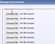
You can try upload pictures directly from your computer.
See and click in 1~4 order. Make Attached Thumbnails
That the best method if you use other method your images is only for some days visible and disappear after.
Have a nice day 🙂
Attachments


Hi guys
Anybody for selling V-fet? Or set with boards
thanks
Hello Platon Rado
Do you know DiY SIT-3 version ?
Good news from Mr Pass
What To Do With Those 2SJ28's
Maybe that is another solution for you
one superb alternative amp build project 😉
Hi Nelson,
Could you please take a look at post # 3135
Some of the numbers were erased but I believe I'm seeing 87 on one of them. What would be your advice?
Thanks!
Do
Could you please take a look at post # 3135
Some of the numbers were erased but I believe I'm seeing 87 on one of them. What would be your advice?
Thanks!
Do
Hi DO,
Nelson's original suggestion will work just fine. The exact initial voltages are not important
as long as they are high enough to keep the Vfets from drawing much current.
Given your pictures seem to show the labels to be 8X, you can pretend they
are 90, and set the initial voltages at +/10V.
Cheers,
Dennis
- Home
- Amplifiers
- Pass Labs
- Sony vFET Amplifier Part 2