Hi Neb ,
I ran the last version of Oled ΗOLD version and I have these problems..
at line 1718 drawBar();
When I get on // drawBar(); the code run completely but it does not show me the volume bar ...at screen oled.
Also the volume up goes up with streps instead volume down goes down very well .
Any suggestion ?
Take ssd1306ascii folder from my drive and use arduino ide 1.6.9. I don't have these problems with same code.
Sent from my MI 6 using Tapatalk
Sent from my MI 6 using Tapatalk
A late Starter ....
This looks like a great project that I have been following for a while.
The bones of my project are finally coming together, unfortunately I have been distracted for several months, but now have some time to continue.
Thank you to a very generous Aussie for the donation of the controller board, who was probably wondering if this project would ever materialise 😕
The project is to have two inputs, one being a dedicated in case DAC the other being via an external input if required. The internal DAC is a small QDAC a refinement of the ODAC and requires 5 VDC.
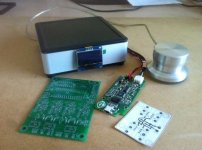
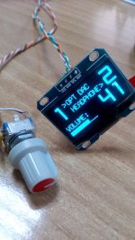
The plan is to locate both the Controller Board, DAC and I/O board in the case, use a 1.3 OLED screen and have a case mounted Rotary Encoder, but also an external encoder based on a converted Griffin PowerMate. The parts are in the attached photo.
The Rotary Encoder has two GND connections, is it OK to just connect the two GND connections together as this would save one cable to the Griffin Powermate’s encoder ?
I am planning to locate the power supply in an external case.
I noticed in post #168, 169 the possibility of using 5VDC relays, in which case if I was to use 5VDC for the relays, could I use the same Power Source for the DAC or would there be to much noise introduced into the DAC ?
I believe all relays run from the same power source, both the I/O board and the 3 Controller relays ?
The BOM transformer is not available from my preferred supplier. One of the transformer attributes seems to be a “split bobbin” for improved electrical shielding, is this the same as a “double section bobbin” or even “Isolated” ?
Such as this | 2 x 12V ac PCB Mount PCB Transformer, 10VA |
Thank you for any thoughts
This looks like a great project that I have been following for a while.
The bones of my project are finally coming together, unfortunately I have been distracted for several months, but now have some time to continue.
Thank you to a very generous Aussie for the donation of the controller board, who was probably wondering if this project would ever materialise 😕
The project is to have two inputs, one being a dedicated in case DAC the other being via an external input if required. The internal DAC is a small QDAC a refinement of the ODAC and requires 5 VDC.
The plan is to locate both the Controller Board, DAC and I/O board in the case, use a 1.3 OLED screen and have a case mounted Rotary Encoder, but also an external encoder based on a converted Griffin PowerMate. The parts are in the attached photo.
The Rotary Encoder has two GND connections, is it OK to just connect the two GND connections together as this would save one cable to the Griffin Powermate’s encoder ?
I am planning to locate the power supply in an external case.
I noticed in post #168, 169 the possibility of using 5VDC relays, in which case if I was to use 5VDC for the relays, could I use the same Power Source for the DAC or would there be to much noise introduced into the DAC ?
I believe all relays run from the same power source, both the I/O board and the 3 Controller relays ?
The BOM transformer is not available from my preferred supplier. One of the transformer attributes seems to be a “split bobbin” for improved electrical shielding, is this the same as a “double section bobbin” or even “Isolated” ?
Such as this | 2 x 12V ac PCB Mount PCB Transformer, 10VA |
Thank you for any thoughts
Attachments
This looks like a great project that I have been following for a while.
The bones of my project are finally coming together, unfortunately I have been distracted for several months, but now have some time to continue.
Thank you to a very generous Aussie for the donation of the controller board, who was probably wondering if this project would ever materialise 😕
The project is to have two inputs, one being a dedicated in case DAC the other being via an external input if required. The internal DAC is a small QDAC a refinement of the ODAC and requires 5 VDC.
The plan is to locate both the Controller Board, DAC and I/O board in the case, use a 1.3 OLED screen and have a case mounted Rotary Encoder, but also an external encoder based on a converted Griffin PowerMate. The parts are in the attached photo.
The Rotary Encoder has two GND connections, is it OK to just connect the two GND connections together as this would save one cable to the Griffin Powermate’s encoder ?
I am planning to locate the power supply in an external case.
I noticed in post #168, 169 the possibility of using 5VDC relays, in which case if I was to use 5VDC for the relays, could I use the same Power Source for the DAC or would there be to much noise introduced into the DAC ?
I believe all relays run from the same power source, both the I/O board and the 3 Controller relays ?
The BOM transformer is not available from my preferred supplier. One of the transformer attributes seems to be a “split bobbin” for improved electrical shielding, is this the same as a “double section bobbin” or even “Isolated” ?
Such as this | 2 x 12V ac PCB Mount PCB Transformer, 10VA |
Thank you for any thoughts
That should work just fine. I am using similar one from RS, 2x6V in series, 10VA.
VC 10/2/6 | 6V ac 2 Output Through Hole PCB Transformer, 10VA | Block
I have another completed, calibrated and tested all-in-one pcb for sale. I can only send it today or when I am back from holiday in September, so be quick if you want it.


Sent from my MI 6 using Tapatalk
Sent from my MI 6 using Tapatalk
Last edited:
The Rotary Encoder has two GND connections, is it OK to just connect the two GND connections together as this would save one cable to the Griffin Powermate’s encoder ?
I noticed in post #168, 169 the possibility of using 5VDC relays, in which case if I was to use 5VDC for the relays, could I use the same Power Source for the DAC or would there be to much noise introduced into the DAC ?
I believe all relays run from the same power source, both the I/O board and the 3 Controller relays ?
Thankyou ZDR.
Does anyone else have some guidance on my other questions please ?
Thankyou ZDR.
Does anyone else have some guidance on my other questions please ?
Hi in my second Arduino based LDR volume always first version like yours i use 5V relays and 5V regulator on PSU no problem ..
Attachments
Last edited:
Hi in my second Arduino based LDR volume always first version like yours i use 5V relays and 5V regulator on PSU no problem ..
Great thanks, that was for both sets of relays on the processor and input/output boards ?
Also do you recall now many wires you connected to the Rotary Encoder, was it 4 or 5 ?
Hi
4 wire for the rotary encoder.The gnd goes to one leg of the push switch and the centre of the three legs.
only tested for the main board , i have latching relays 4.5V for my the input-board but i dont have tested with 5.0 Volt.
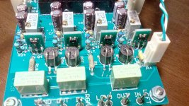
Arduino based LDR volume and source selection controller
4 wire for the rotary encoder.The gnd goes to one leg of the push switch and the centre of the three legs.
only tested for the main board , i have latching relays 4.5V for my the input-board but i dont have tested with 5.0 Volt.
Arduino based LDR volume and source selection controller
Last edited:
I have another completed, calibrated and tested all-in-one pcb for sale. I can only send it today or when I am back from holiday in September, so be quick if you want it.
Sent from my MI 6 using Tapatalk
PM sent!
Anyone interested in a modified PCB/GERBER files for the controller that uses VN2222LL-G instead of 5LN01SP?
I have another fully assembled and tested board available, if someone is interested.
You've got PM 🙂
Anyone interested in completely finished device? I sold active speakers this was actually built for, so no need for it anymore.

- Home
- Source & Line
- Analog Line Level
- Arduino based LDR volume and source selection controller