my mosfet buffer (voltage amplification =1), 180W@4R, thd 20kHz < 0.01% (at any power level into 4R)
Superb, simply beautiful, excellent job. 🙂
my mosfet buffer (voltage amplification =1), 180W@4R, thd 20kHz < 0.01% (at any power level into 4R)
What does your buffer circuit look like ? If you don't mind sharing you could post it here. It isn't just a source follower as I can see drivers etc.
240/9240 ?
Thanks.
Last edited:
What does your buffer circuit look like ? If you don't mind sharing you could post it here. It isn't just a source follower as I can see drivers etc.
240/9240 ?
Thanks.
http://www.diyaudio.com/forums/solid-state/286565-hec-amp.html#post5104272
Hey LKA, thanks for that. Great build. Beautifully laid out pcb !
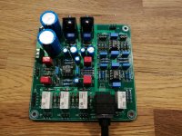
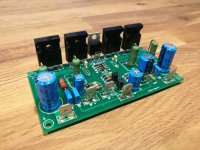
Simple and cheap amplifier boards, just waiting for transistors to arrive.
Ready for testing.
Attachments
Ready for testing.
This is the year 2017 why people continue to make the same mistakes ?
This is the year 2017 why people continue to make the same mistakes ?
Why are people still replying to posts with no constructive text at all?
Why are people still replying to posts with no constructive text at all?
exactly .. and you also notice its all ways the same small group of forum members 😡
the clue is in the forum title ... let me spell it OUT ! ..... D .. I ... Y
members can only learn from feedback from more experienced constructors
Last edited:
Why are people still replying to posts with no constructive text at all?
From what I see right away - speaker return (SP -) must be connected to the "main ground" on PSU, not on the board. Otherwise, high currents from the speaker influence your local ground here. Regardless the fact that these points are connected with wire, the ground on the board and the ground on PSU are very different points electrically - that's where the ground wire resistance leads to additional distortion, ground loops, etc.
Put an extra large conductor size from the gnd board to gnd PSU and the problems will be much smaller. Both connections must be very tightened
This is the year 2017 why people continue to make the same mistakes ?
and the mistakes are ? 😱
1) Tip 142-147 are not audio transistors these are for low pitch switching application with unknown ft and cob datasheet describes them as solenoid drivers .
2) There is no known application that operates with parallel darlingtons there is less than a handful of commercial amplifiers made like that but known stability issues due to very high beta and thermal tracking issues create a long history of failure . Even the AB 100 designed by Pass is under question for both stability and performance by me in the first place but also i feel from other members i find weird that its a Pass diy project but it seems that not many is willing to construct ...Rare for a pass design .
3) in most known applications miller caps of the region of sometimes 680pf is required to keep darlingtons operating safe from oscillation well known sonic killers and in your case BIG TIME NO ceramic capacitors are not suitable for such an application both from performance and voltage aspects ....I have to admit that i have seen so far 2-3 circuits that operate without them the AB 100 included but stabilty without them for me is under question .
4) in most known circuits ballast resistors are in the area of 0.68R and often above to 1R10W to manage to achieve some balance between just 2 outputs imagine with 4 Imagine speed with 0.68R resistors That on its own is a pointer to explain to you the very high beta and very poor thermal tracking issues around those transistors .
5) East electronics is a repair firm Meaning that when you see 1830 audio machines last year only yes you have very nice statistics available If you like to have darlington failure rates i will make them available to you ....
Finally diy doesn't simply mean see a simple circuit feed it to a PCB software design a neat PCB around it and you are done ....A bit of reading a bit of study especially around the choice of output will eventually get you there ....
Make a forum search you will find plenty of articles related to 142-147 by me ...Some of them include nice smoky pictures from the failure history ....
Enjoy
This is the year 2017 why people continue to make the same mistakes ?
maybe because we have many thousands of Members who refuse to read.Why are people still replying to posts with no constructive text at all?
I do not understand why many people just build something. About 90% of all circuits are crap or have very low quality. Unfortunately, few people have the opportunity to measure correctly.
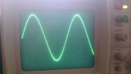
I have build these pcb's before and did some measurements.
Found an old picture of 1KHz signal just before clipping (on +/- 40V powersupply)
I use them as amp for some small PA monitors for several years, no issues untill now. No need for high quality, just low cost.
Found an old picture of 1KHz signal just before clipping (on +/- 40V powersupply)
I use them as amp for some small PA monitors for several years, no issues untill now. No need for high quality, just low cost.
Attachments
and the mistakes are ? 😱
I started to read then got bored ...
I do not understand why many people just build something. About 90% of all circuits are crap or have very low quality. Unfortunately, few people have the opportunity to measure correctly.
Ok .. last post from me on this subject as this is a gallery picture section
If people make stuff .. may be crap but they are having fun and learning that is the point. I can remember my 1st build that actually worked and was very pleased with the result, this can be very rewarding. And the more you build you gain more experience and the quality will improve. I am sure we have some very knowledgeable experts on this site but have never made one single project so always easy to Criticise ... but this is fine in a constructive manner
regards
Last edited:
- Home
- Amplifiers
- Solid State
- Post your Solid State pics here