Excuse me, but for my info, what is a bolt grower?
1.5Nm is a bit on the higher side. As per on semi guidelines, the recommended torque for to-247, to-3p, its 0.8Nm to 1 Nm.
I am not a prolific builder and neither do I have a torque wrench, if the mounting method used by ESP is good enough to be recommended by him, it's good enough for me.
Hey it's diy, if it fails, who cares? Let's build another one.
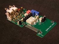
Another small project for early mornings. Modular input selector, any input card as required can be prepared. I must finish up bluetooth to i2s converter for the DAC too. No time for the holidays left...
Regards
Regards
Attachments


Transistor matching.

Double sided double PASS ZEN AMP (2x60W) made with TCI 3.00
http://b.urbani.free.fr/pagetci/tci.htm

Four cards of 2x60... 8x60W

The four cards in the enclosure.

Two cards with their capacitors bank.

Closed enclosure of 8 channels ZEN AMP.


Double sided double PASS ZEN AMP (2x60W) made with TCI 3.00
http://b.urbani.free.fr/pagetci/tci.htm
Four cards of 2x60... 8x60W

The four cards in the enclosure.

Two cards with their capacitors bank.

Closed enclosure of 8 channels ZEN AMP.


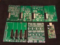
Home made PCB
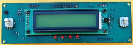
Thank you guys for the good comments. Here is the PCB assembled, the electrical test went OK, only one of the 136 via holes found non-soldered. This is the control PCB of the new integrated DAC - Amplifier. You can see two rotary encoders (switch equipped), a 2 X 20 Display, the IR receiver of remote control and 4 LED indicators. The left encoder is for input selection and when pressed it turns the unit in STBY mode. The right encoder is for volume control and when pressed enables the MUTE function. From the left, the 1st LED indicates STBY, the 2nd indicates ERROR of the left channel, the 3rd ERROR of the right channel and the 4th MUTE when activated. On the solder side, you can see the main processor PIC16F1789 (nice MCU with IOC and pull-ups available almost in all pins) and the I/O port expander PCA9535. The power amplifier will be fully balanced, driven directly from the balanced outputs of the DAC converter. The rest boards of the project will follow in a couple of weeks. Thanks again.
Thank you guys for the good comments. Here is the PCB assembled, the electrical test went OK, only one of the 136 via holes found non-soldered. This is the control PCB of the new integrated DAC - Amplifier. You can see two rotary encoders (switch equipped), a 2 X 20 Display, the IR receiver of remote control and 4 LED indicators. The left encoder is for input selection and when pressed it turns the unit in STBY mode. The right encoder is for volume control and when pressed enables the MUTE function. From the left, the 1st LED indicates STBY, the 2nd indicates ERROR of the left channel, the 3rd ERROR of the right channel and the 4th MUTE when activated. On the solder side, you can see the main processor PIC16F1789 (nice MCU with IOC and pull-ups available almost in all pins) and the I/O port expander PCA9535. The power amplifier will be fully balanced, driven directly from the balanced outputs of the DAC converter. The rest boards of the project will follow in a couple of weeks. Thanks again.
Attachments

Last edited:
Hi Sakis. Nice to see you too, again. Thanks for the comment. I hope everything is fine with you (included your family). I will give you a call next days.
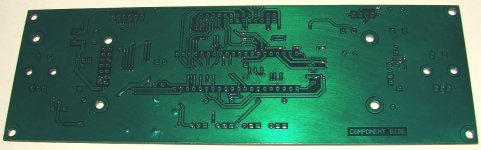
185 X 60mm two layers homemade PCB with 136 vias. Mixed THT and SMT components. BUNGARD presensitized PCB. The green coating is also BUNGARD.
you are fooling me with those PCB's😉, who needs PCB houses if one has such skill in home made PCB's. Congrats

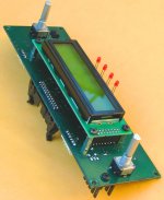
Thanks Prasi. Now i have to write some code in micro, to test if the display and the encoders (because are bought from e-bay) are working properly. It is also a good chance to test a modified version of the RC5 remote control protocol that i obtained before few months. I will post you pics with the control board in action.
- Home
- Amplifiers
- Solid State
- Post your Solid State pics here