My eyesight is not exactly 20:20, so it was driving me bonkers. T1-5 soldered on now. Permanently...
Can I take my 40V AC direct from the AC side of the rectifier? Just need to lashup some wiring now. POPS
Can I take my 40V AC direct from the AC side of the rectifier? Just need to lashup some wiring now. POPS
Can I take my 40V AC direct from the AC side of the rectifier?
Yes, that's how it is supposed to be connected.
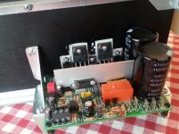
Phew... one Q-Watt PCB completely finished and integrated onto the heatsink, and even bolted back into the case. That was a pig of a job because the PCB covers the critical bolt-holes.
Just not sure of the 40V AC connections. My transformer has 2x 0-40V (approx) so from where should I take the three (+ 0 - ) connections to the Q-Watt? Is the Zero just connected to chassis? Remember I have not configured my transformers with centre tap configuration... but instead with parallel outputs to each rail. Please help!
Pops.
Attachments

Last edited:
Just not sure of the 40V AC connections.
See attached picture.
Attachments
Delange to the rescue!
What would we do without you?
Helped me too in time of need.
Result? A superb sounding Q-watt!
What would we do without you?
Helped me too in time of need.
Result? A superb sounding Q-watt!
But chaps.... is this centre-tap AC configuration (-40 0 +40) compatible with my current power supply layout, using a rectifier per secondary to power each rail.
You are suggesting I must short together one + and - AC line. I think this will break my power supply(?) Each rectifier sees 40V AC currently, not 80V AC. You can refer back to post 170:
http://www.diyaudio.com/forums/chip-amps/301100-my-q-watt-project-17.html#post4998527
Do I need to change my whole PS architecture to 'centre-tap' (which has been suggested more than a few times) or is it possible to have parallel outputs AND centre-tap outputs from the transformer?
Last edited:
But chaps.... is this centre-tap AC configuration (-40 0 +40) compatible with my current power supply layout, using a rectifier per secondary to power each rail.
You are suggesting I must short together one + and - AC line. I think this will break my power supply(?) Each rectifier sees 40V AC currently, not 80V AC. You can refer back to post 170:
http://www.diyaudio.com/forums/chip-amps/301100-my-q-watt-project-17.html#post4998527
Do I need to change my whole PS architecture to 'centre-tap' (which has been suggested more than a few times) or is it possible to have parallel outputs AND centre-tap outputs from the transformer?
Could you post a schematic of your power supply. This way I can show you how to hook it up.
Hi delange,
Its the same as post 170:
http://www.diyaudio.com/forums/chip-amps/301100-my-q-watt-project-17.html#post4998527
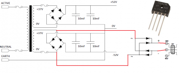
Voltages are a smidge higher, but the architecture is the same. At the moment I have one bridge rectifier per rail 0-40V AC. Everything in the PS is flexible if need be...
And please ignore the fuses. They don't exist.
Thanks! Pops.
Its the same as post 170:
http://www.diyaudio.com/forums/chip-amps/301100-my-q-watt-project-17.html#post4998527
Voltages are a smidge higher, but the architecture is the same. At the moment I have one bridge rectifier per rail 0-40V AC. Everything in the PS is flexible if need be...
And please ignore the fuses. They don't exist.
Thanks! Pops.
Last edited:
Hi delange,
Its the same as post 170:
http://www.diyaudio.com/forums/chip-amps/301100-my-q-watt-project-17.html#post4998527
Voltages are a smidge higher, but the architecture is the same. At the moment I have one bridge rectifier per rail 0-40V AC. Everything in the PS is flexible if need be...
And please ignore the fuses. They don't exist.
Thanks! Pops.
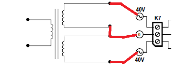
Hi Pops, without changing anything to your power supply setup, you could connect it like in the attached picture; using only one of the secondary winding. You'll need an additional rectifier because otherwise you would end up with an half wave rectifier. The opto-coupler is fast enough to follow the 50 Hz mains frequency and that would probably make the relais zoom (zooming sound).
With the setup as in the attached picture the voltage guard works in the same way as using the two secondary windings (the original intent of the Q-Watt voltage guard). By using a rectangle rectifier you could fix the rectifier with its + and - leads in K7 and solder two wires n the AC leads. That construction would physically be stable enough.
Attachments
you have to make a TWO WIRE connection from the transformer to the auxiliary circuit.
The TWO WIRE rule applies to all inter-module connections.
Take one tapping off each end of ONE winding.
Take that AC to the auxiliary board using a twisted pair. It will emit emi and you need to attenuate that emi as much as possible.
The TWO WIRE rule applies to all inter-module connections.
Take one tapping off each end of ONE winding.
Take that AC to the auxiliary board using a twisted pair. It will emit emi and you need to attenuate that emi as much as possible.
Thanks delange.With the setup as in the attached picture the voltage guard works in the same way as using the two secondary windings (the original intent of the Q-Watt voltage guard). By using a rectangle rectifier you could fix the rectifier with its + and - leads in K7 and solder two wires n the AC leads. That construction would physically be stable enough.
Would this feed DC into the Q-Watt AC input?
I'll probably just rip out out of the rectifiers and go for a more conventional PS with single +/- 40V rectifier per channel. Don't really want to add any new components. Should get an extra 0.9V DC too. Just delays things again! I did try this months ago, but the wiring was (very) temporary.
One of the reasons I avoided connecting the transformer centre-tap is that I couldn't think of suitable hardware. Just easier to connect directly to a rectifier. I might try and find some multi-way 6.25mm male tab junctions.
How is a bulletproof three-way junction normally made?
Pops.
Thanks Andrew. Problem is (as I see it) that simply connecting both sec windings to the Q-Watt ~ 0 ~ AC input (2x two wire connections) would involve joining the two sec windings. Surely this would corrupt the existing parallel PS architecture. The two sec windings are separate at present until after the DC filter caps.you have to make a TWO WIRE connection from the transformer to the auxiliary circuit.
The TWO WIRE rule applies to all inter-module connections.
Take one tapping off each end of ONE winding.
Take that AC to the auxiliary board using a twisted pair. It will emit emi and you need to attenuate that emi as much as possible.
If the most elegant solution is to change to a centre tap architecture then I'm happy to hear it.
Pops.
No need to use the rectifier. Just connect one phase between 40V and 0. Check the schematic for a better understanding of the circuit.
Hi Mark,No need to use the rectifier. Just connect one phase between 40V and 0. Check the schematic for a better understanding of the circuit.
The Q-Watt AC input needs three connections: [~ 0 ~].
So this requires more than just 40V & 0V. What do you mean exactly?
Sorry if I misunderstood. I just want to figure if there's an easy workaround or if I need to tearup my PS wiring.
Thanks - Pops
Would this feed DC into the Q-Watt AC input?
The "AC input" (K7) is converting the AC to DC anyway (D3 and D4). So it is not an issue to inject DC on K7.
I'll probably just rip out out of the rectifiers and go for a more conventional PS with single +/- 40V rectifier per channel.
Yes, by using a conventional wiring of the secondaries you don't need the additional rectifier. The only effort is to rewire the power supply.
One of the reasons I avoided connecting the transformer centre-tap is that I couldn't think of suitable hardware. Just easier to connect directly to a rectifier.
You could use a copper plate or bar to create the GND connection. Your buffer caps could be mounted with one of their terminals directly to the copper plate. The "CT" connection you create by wiring the two wires from the secondaries also connect to the copper plate. This is very common practice.
If you look at the schematic, D3 and D4 connect together to charge C14. If you only connect one of the transformer secondaries it should still switch IC3.
Yes but that will result in a half wave rectifier (since you will only se one of the two diodes). I haven't tried it but possibly this will make the relais switch at the rate of 50 Hz resulting in a buzzing noise.
- Home
- Amplifiers
- Chip Amps
- My Q-Watt project