Just curious of you guys that have tried these which sounds the best?
Tpa3118 Sanwu pbtl
Tda8932 mono
tda2030a mono
I've only listened to 3116 (which has identical silicon) and in stock form the TDA8932 beats it on bass, but loses out on HF cleanliness. TDA2030A loses out across the board to both these classD chips but does have cleaner HF than stock TDA8932. The trick with the 8932 is to clean up the analog supply (pin 8) with better filtering, it then stomps ahead of the other two in everything.
How to do this?I've only listened to 3116 (which has identical silicon) and in stock form the TDA8932 beats it on bass, but loses out on HF cleanliness. TDA2030A loses out across the board to both these classD chips but does have cleaner HF than stock TDA8932. The trick with the 8932 is to clean up the analog supply (pin 8) with better filtering, it then stomps ahead of the other two in everything.
Thank you!
Trimis de pe al meu SM-G925F folosind Tapatalk
Following up I do think this amp has lower noise and better low level detail than my wiener monos, but not as full in low frequencies. Seems to have a little better separation of instruments and depth. However, the monos have more bass output. Otherwise the 3251 has the same sonic attributes. The 3251 has more power though and since I may pursue more power hungry speaker builds in the future, I will probably keep it as my main Amp! 😎
Are you talking about better inductors if so which in particular?
Scott
Scott
I've only listened to 3116 (which has identical silicon) and in stock form the TDA8932 beats it on bass, but loses out on HF cleanliness. TDA2030A loses out across the board to both these classD chips but does have cleaner HF than stock TDA8932. The trick with the 8932 is to clean up the analog supply (pin 8) with better filtering, it then stomps ahead of the other two in everything.
How to do this?
Thank you!
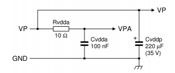
There are various ways of addressing this. The simplest of all is to increase the value of Cvdda which is 100nF in the application schematic.
The next step up is to design an LC filter - meaning Rvdda is replaced with an inductor.
Beyond this its possible to use an IC regulator like LM317, preferably preceded by an LC or RC filter to eliminate the highest frequencies.
I have a hunch that the optimum solution will involve a discrete regulator and LC filter, but that's something to try when I build my next TDA8932 prototype amp.
@Scott - no, I haven't focussed on getting better inductors. When I've tried lower loss Ls I've struggled to notice any improvement. Contrast that with upgrades to the supplies which are instantly noticable.
Attachments
So basically changing the 5 100uf caps for 220uf correct ?
Scott
QUOTE=abraxalito;5077495]There are various ways of addressing this. The simplest of all is to increase the value of Cvdda which is 100nF in the application schematic.
The next step up is to design an LC filter - meaning Rvdda is replaced with an inductor.
Beyond this its possible to use an IC regulator like LM317, preferably preceded by an LC or RC filter to eliminate the highest frequencies.
I have a hunch that the optimum solution will involve a discrete regulator and LC filter, but that's something to try when I build my next TDA8932 prototype amp.
@Scott - no, I haven't focussed on getting better inductors. When I've tried lower loss Ls I've struggled to notice any improvement. Contrast that with upgrades to the supplies which are instantly noticable.[/QUOTE]
So basically changing the 5 100uf caps for 220uf correct ?
No, I've experimented with increasing the main supply capacitance (which means the caps connected to pins 20 & 29 on the IC) and while it makes an improvement for sure, the low hanging fruit is on pin 8 (the signal circuitry supply, not the power stage supply).
so what is that pin 8 cap marked as on the board?
No, I've experimented with increasing the main supply capacitance (which means the caps connected to pins 20 & 29 on the IC) and while it makes an improvement for sure, the low hanging fruit is on pin 8 (the signal circuitry supply, not the power stage supply).
However those aren't the pins I'm talking about on the TDA8932, which is what @bigaudioscotto is asking about.
I'd agree that discussions about TDA8932 would be better off confined to its own thread though.
I'd agree that discussions about TDA8932 would be better off confined to its own thread though.
so what is that pin 8 cap marked as on the board?
Best move the discussion to one of the TDA8932 threads - for example this one : http://www.diyaudio.com/forums/class-d/277130-fasten-seat-belts-tda8932-pessimistic-review-9.html
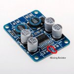
The photo shows 103 marking on the resistor which is 10K ohms. It's probably connected across one of the inputs to ground. Easy enough to check with a multimeter. If so it would be advisable to fit one otherwise the input impedance will differ between channels. You could use a 1/8W through hole resistor across the input terminals if SMD is an issue.
10k I believe is normally there, you can see on other 3 ampboards? Only if you want to use mute pads, you need a connection/resistor there.
edit: It connects gvdd, 6 or 7Vdc, to one of the mute pads, when mutepads are connected together that Vdc gets to mutepin and tpachip will mute. Doesn't affect inputsignal.
edit: It connects gvdd, 6 or 7Vdc, to one of the mute pads, when mutepads are connected together that Vdc gets to mutepin and tpachip will mute. Doesn't affect inputsignal.
Last edited:
Turn on thump ?
Hey guys I just got a pair of the sanwu tpa3118 pbtl boards up and running
They sound great but what is the fix for the turn on thump a simple on off
Switch connected to mute or what ?
Regards
Scott
Hey guys I just got a pair of the sanwu tpa3118 pbtl boards up and running
They sound great but what is the fix for the turn on thump a simple on off
Switch connected to mute or what ?
Regards
Scott
Sorry I don't fully understand that diagram
Could you please tell me what I do
To solve turn on thump?
Could you please tell me what I do
To solve turn on thump?
Last edited:
Ehrm... The simplest solution is in the last photo - a resistor, a capacitor and a Schottky diode.
The pin functions and numbers can be found in the TPA3118 datasheet.
The pin functions and numbers can be found in the TPA3118 datasheet.
So I take it you cannot put a simple on off switch wired on the mute pins
And just flip that on after power up to stop the turn on pop ?
And just flip that on after power up to stop the turn on pop ?
Last edited:
- Home
- Amplifiers
- Class D
- Cheap TPA3118D2 boards, modding them and everything that comes with it