As a matter of fact is 2x (25V x 5A) = 250VA 🙂 (because needed voltage is +/- xxV)25v x 5A= 125VA just a toy ...you need min 300VA or better two 200VA one for side
In case of +/- 31Vdc (2x 22Vac), doing the math, result a 350VA trafo (for both cannels).
This was the minimum value for the current and power the trafo must suport.
A 600VA trafo was recomended by Eduard, for a serious power reserve.
Yes, a 600VA trafo with 2 x 22Vac is probably quoted at 8A.
Sorry, Vishalk, in this case you were right before when estimated 7A.
Last edited:
The plan is to get a Trafo which is 600va and different voltages.
it seems i should have 12-22-26-30-0-30-26-22-12, and obviously 8A on those windings except for the 12v which can be 1A.
Im still confused about the output from the transformer. I would only need 1x12vac. Would i need 2x22-26-30? Dual wound?
http://www.yaag.biz.id/index.php/en/2015/05/22/power-supply/
nice article
Still having a hard time sourcing double c core (ED type) and R core, waiting for a few enquiries. If all else fails ill have to go with an EI.
As a matter of fact is 2x (25V x 5A) = 250VA 🙂 (because needed voltage is +/- xxV)
In case of +/- 31Vdc (2x 22Vac), doing the math, result a 350VA trafo (for both cannels).
This was the minimum value for the current and power the trafo must suport.
A 600VA trafo was recomended by Eduard, for a serious power reserve.
Yes, a 600VA trafo with 2 x 22Vac is probably quoted at 8A.
Sorry, Vishalk, in this case you were right before when estimated 7A.
Last edited:
No, not exactly like that.
Do not make any confusion between AC and DC. DC is AC voltage multiplied by 1,4142135 (square root of 2).
When speaks of trafo we always refer to AC. When speaking of supplying audio module we refer to DC.
For instance, if you need +/-31Vdc that means 2x22Vac. And for a 600VA trafo that will probably quoted at 8A. (Of course you will not use more than 320-350VA, the rest is the "power reserve")
You don't need 12-22-26-30-0-30-26-22-12 voltage windings.
You need a low current (0,5-1A) 13,5Vac separate winding and two high current (8A) identical winding for 20-22-25Vac.
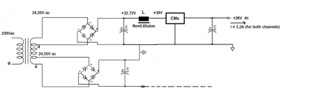
I will post 2 pictures for easy understanding the voltage droped on each element of the PS.
In both cases I assumed 2Vdc lost on rectifying diodes. If you use Schottky diodes you will probably lose only 1.1-1.2Vdc on them.
Do not make any confusion between AC and DC. DC is AC voltage multiplied by 1,4142135 (square root of 2).
When speaks of trafo we always refer to AC. When speaking of supplying audio module we refer to DC.
For instance, if you need +/-31Vdc that means 2x22Vac. And for a 600VA trafo that will probably quoted at 8A. (Of course you will not use more than 320-350VA, the rest is the "power reserve")
You don't need 12-22-26-30-0-30-26-22-12 voltage windings.
You need a low current (0,5-1A) 13,5Vac separate winding and two high current (8A) identical winding for 20-22-25Vac.
I will post 2 pictures for easy understanding the voltage droped on each element of the PS.
In both cases I assumed 2Vdc lost on rectifying diodes. If you use Schottky diodes you will probably lose only 1.1-1.2Vdc on them.
Attachments

Last edited:
you are showing 0V in the centre of symmetrical tappings.The plan is to get a Trafo which is 600va and different voltages.
it seems i should have 12-22-26-30-0-30-26-22-12, and obviously 8A on those windings except for the 12v which can be 1A..............
That will be wound as 30, 26, 22, 12, 0 12, 22, 26, 30Vac
The lowest voltage tapping is next to the 0V centre tap.
This first winding MUST pass all and any current that any other tap may be required to deliver. i.e. the centre winding must be rated for the highest current.
If you only need a dual polarity high current supply and a single polarity low current supply for auxiliaries, then it is better to separate these two requirements.
Specify a dual secondary for the high current supply and an extra low current single winding at the voltage you think you need.
You can even add the low voltage secondary winding to a standard dual secondary toroid yourself.
A 0.5mm diameter enamelled copper wire can be wound around the toroid, (if it is the open type). This 0.5mm copper is rated at roughly 600mAac. If you know that all your auxiliaries need a bit more, then buy a thicker enamelled wire, 0.6mm (870mAac), or 0.7mm (1190mAac) diameter copper.
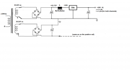
Andrew, thank you for correction. I was concentrated on the dc voltage and overlook the transformer ambiguous draw (took the first draw at hand and modified it). I apologies for my inattention.Do not copy the post223 schematics. Both are wrong !!!!!
Now it is correct - and concord with the text I wrote.
Attachments

Last edited:
Where can you buy the boards? Or do you have the files that i can get it made?
Thanks
V
Look around in the thread - there are several versions be different people available.
http://www.diyaudio.com/forums/solid-state/297921-jumas-easy-peasy-capacitance-multiplier-23.html
Try PM with member Idefixes. I got a couple from him and they are nice and low cost.
Hello,
Did read some French post on this amp. There is still loads of info on this amp that stays in France LOL.
I read somewhere that people did use short wires to connect the power transistors to the circuit. This gives the possibility to create some extra distance between the two to keep them a little cooler.Some people think the soldering pads could be damaged by temperature changes when mounted directed to the heatsink.
They also write about keeping some small transistors at the same temperature by '' glueing'' them together to reduce dc at output.......
Greetings, Eduard
Designing soldering pads large enough to be able to dissipate excess heating is a pcb designing demand.
If pad are small and fear exists, critical solders can be made by solder with Ag (with a significantly higher melting temperature), and they will resist much better in time.
Keeping small transistors close together is called "couplage thermique", and its usually made with a small piece of heat shrinking varnish. Usually meet in DIY audio amps.
I've talked to some people who like a capacitance multiplier with this amp. I remained to be convinced that it doesn't just add coloration.
It will certainly change the sound in a rather dramatic way. Whether this is to your liking or not is another question.
Power Supply choice.
After a great deal of thought and research my ideas are going this route for the power supply.
1. Dual bridge Rectifier
Depending on choice of transformer (this is my main issue at the moment) It will either be one transformer or two. I have now managed to source two really good companies to make me an R-Core and/or EI dedicated for audio use (so use of shielding, bifilar winding etc)
So it could be one big transformer going through a dual bridge rectifier or two transformers going through, again, through two separate dual bridge rectifiers for each amplifier board. Which becomes more expensive 🙁. Now i know this is supposed to be the best way, but surely just a modern single bridge rectifier is more than fine??
Just means i have to wait longer each month for pay day to spend some hard earned money on this project.
I just purchased a pair of LUNDAHL LL2733! So they are on there way. If i go dual power supply does that mean i have to buy another pair? hahahaha i bloody nope not! Excuse my ignorance i am still learning guys.
I don't think i am going to use a cap mulitiplier, going old skool on this one.
Love the thought of some equally spaced big caps, some copper polished copper bus bars and some nice bolts all holding it together.
I think while writing this, one big high quality transformer and a dual bridge rectifier going through the chokes would be the obvious choice.
But hey i'm open to ideas and options 😛
Amplifier chassis is coming along, just ordered some hefty heatsinks and some aluminium sheets. Which also means i have to buy a Drill stand (top drill) and some other handy tools.
Also have to be able to make my own circuit board for the rectifiers and other electronic parts, so looking to learn how to use some form of easy circuit board design software to help. Suggestions? Or make my life easier is there something out on the market i can use? Either way something i have to learn for future projects.
Building a Gainclone chip amp power supply.
This was a very nice read, Building a Gainclone chip amp.
Anyway hope you are all well, and i will be sure to keep you posted.
Keep the ideas and advice coming it's all appreciated.
Last edited:
Two trafo has sense if you want to do a dual mono power supply (PS).
In this case, absolutely every component of the PS must be bought again, because practically there are two PS. The only difference is that the current is half than on the "stereo" PS. That means smaller trafos, smaller rectifier (but not much), smaller capacitors (but not half value) and chokes that admit 1,7A instead of 3,4A.
It's a much more expensive solution.
Because of the high costs of a dual mono PS for a class A amp, I would do that for two monoblocks, but for a stereo amp ... I don't know.
Last edited:
yes you would need another pair of LUNDAHLs. i suggest you go for a proper dual mono or mono-block build. it sure is costly and gonna take some time. even in general most of us have built this over period of few months - more than a year in my case! so take it slow and go for the best approach!
on the other hand, if you are somebody who keeps fiddling with your diy builds after completion and if you are restless now then go for a stereo build for now. later on procure stuff for mono builds - which means you would buy identical components similar to your stereo build - might be overkill but still you'll get more time to procure stuff and satisfaction of not compromising on build!
all the best!
Depending how much you love Hiraga amp sound, a monoblock construction has sense or not, it's subjectively.
A dual mono construction offer much smaller cross talk between channels.
A monoblock construction offer in addition to that a big chance to increase power - may be important or not, depending on the speakers you will use.
Increasing power means that each PS be calculate for a stereo amp (60-70W of class A output power), and that's more money to spent.
Hello,
We start talking about two transformers in order to make it possible to use 2 rectfifiers. This will still need the same number of chokes.
It seems with the kit the OP bought it could be possible to use a seperate power supply for the input stage. I told him by email he should ask his supplier if that could be possible.
Double mono will have impressive looks. But if you want to start bragging you dont wanna build a 30 watt amp. All the stories i heard about this amp are good but it comes down a lot on the power supply.
I seriously believe that choke input could be a big leap.
If giving the input stage its proper power supply could be done it might give a nice improvement too. A small r core, two little chokes and some small caps.......
greetings, Eduard
hi eduard, going by OP's first post his PCB's are from Jim's audio and on those we have an option to provide separate power supply for input stage by default.
hi eduard, going by OP's first post his PCB's are from Jim's audio and on those we have an option to provide separate power supply for input stage by default.
Hello,
The info from the supplier is rather minimal. OP is far from experienced to build this amp so everything must be clear. Did send him some info by email but no reaction so far.
Will start spending time on my own diy.
Will visit this thread in a few weeks time.
Greetings, Eduard
Hello,
The info from the supplier is rather minimal. OP is far from experienced to build this amp so everything must be clear. Did send him some info by email but no reaction so far.
Will start spending time on my own diy.
Will visit this thread in a few weeks time.
Greetings, Eduard
sure. since i've used the same PCBs [version without Kubota regulator] in my build i confirmed it 🙂 . and i'm yet to implement your suggestion of using chokes for DC filter for my build! for sure it'll be my next upgrade!
for now CRC is doing the job.
- Home
- Amplifiers
- Solid State
- Jean Hiraga Super Class A 30w Build