Eduard, no, the purpose of the resistor [of the soft start, be it manual or automatic] is not to make the ac output of the transformer lower, that is a consequence. The purpose is to limit the inrush current.[/QUOTE]
Hello,
Of course it is there to lower the inrush current.
BUT i used mine as a standby option to make it possible to have the amp switched on 24 hours without raising your electricity bill. So to keep the caps charged at 12? volt during standby with minimum current being drawn and by pulling the switch make the amplifier get hot.
I think i told that. If i didnt i d have done it now.
Greetings, Eduard
Ps. i thought we did agree that smps were not designed for the Hiraga lol
Yes, you said it before. I did not make the connection with the soft-start discution.
And yes, in this case, a 220ohm R is a good value.
Of course SMPS were not designed for Hiraga Amps, they start beeing used in audio only some 25 years ago 😛
I am not the one you must convince not to use a SMPS...
Scottjoplin, the Th is changing value very quick, in about 0,2sec is already close to the hot value.
200msec might be a little short for slow charge the capacitors. But with well selected value for the Th, it may be ok.
If relay fails to operate - yes, the R will go hot and burn. But this a way of saying "What if an airplaine will fall on me" ... This is why should be used expensive relays and cheap R 😀
Last edited:
A perfect case of when a cap multiplier is helpful in reducing cost of needed caps. Class A has steady current requirements and here a cap multiplier is well suited. Just have to account for dropout voltage. If using a simple mosfet cap Mx a 4v drop is typical. Just size transformer for +4v more.
http://www.diyaudio.com/forums/solid-state/297921-jumas-easy-peasy-capacitance-multiplier.html
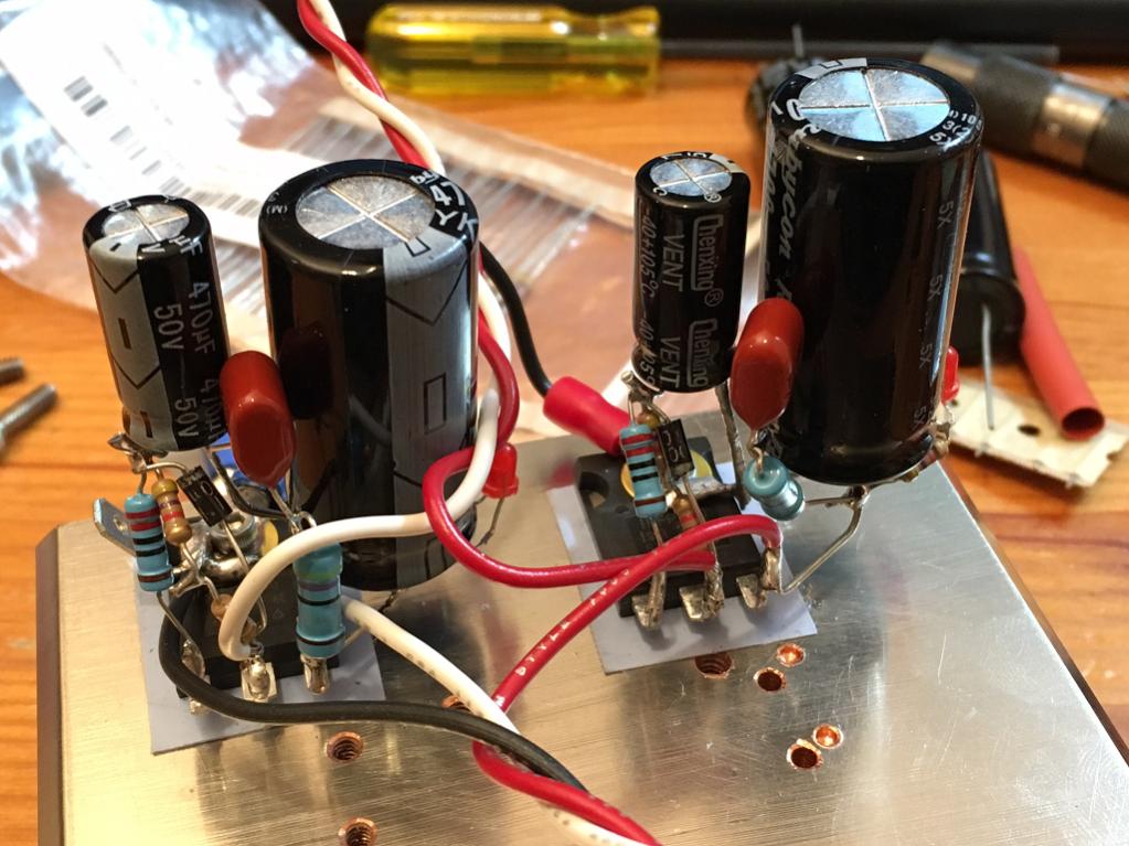
I think PCBs are available from Idefixes. It's so simple you can just P2P it on the mosfet legs. Here is one channel +ve and -ve.
On my 22mF/0.25R/22mF CRC it took 60mV ripple (under 1.2 amp load) down to 0.0mV as measured with Fluke 101.
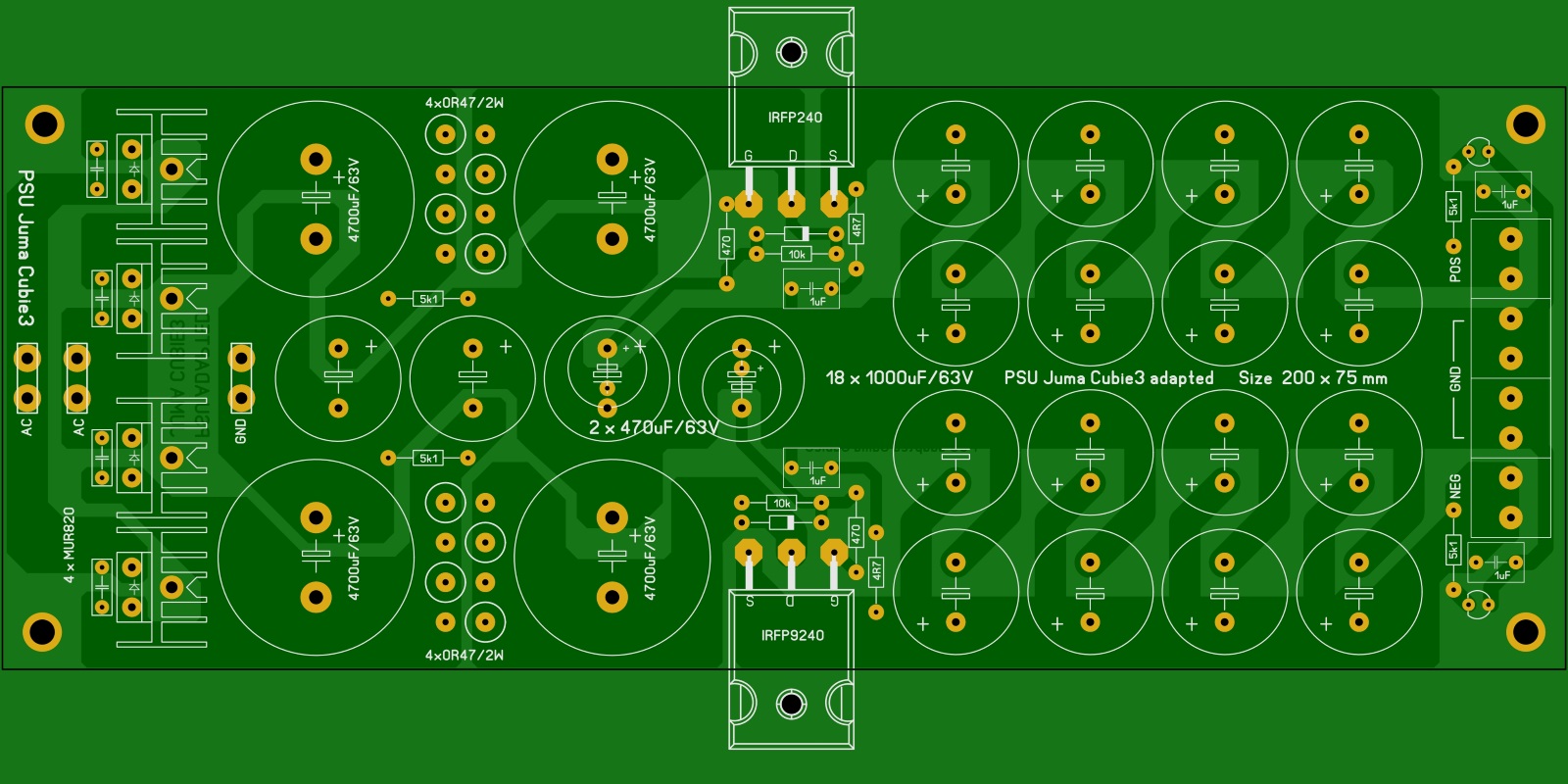
Here is Olafk's layout:
It really does cost less than equivalent caps to get -50dB of ripple rejection.
http://www.diyaudio.com/forums/solid-state/297921-jumas-easy-peasy-capacitance-multiplier.html
I think PCBs are available from Idefixes. It's so simple you can just P2P it on the mosfet legs. Here is one channel +ve and -ve.
On my 22mF/0.25R/22mF CRC it took 60mV ripple (under 1.2 amp load) down to 0.0mV as measured with Fluke 101.
Here is Olafk's layout:
It really does cost less than equivalent caps to get -50dB of ripple rejection.
Last edited:
Why is the first C (C1 & C2) so big ?
And why not a small R between C1/C2 and the cap multiplier ? Would it increase the ripple ?
What are the acoustical effects of using a cap multiplier - on class A amp, of course.
And why not a small R between C1/C2 and the cap multiplier ? Would it increase the ripple ?
What are the acoustical effects of using a cap multiplier - on class A amp, of course.
Last edited:
Personally I prefer classic PS, even for a class A amp (that is more suited for a SMPS than a class AB, because its constant consumption).
What exactly do you mean by "constant consumption"?
A power amplifier will never have a constant consumption because it is driving a speaker at the rhythm of the music. So the current will fluctuate at the rhythm of the music.
The SMPS500R is designed for audio amplifiers including class ab. It can handle lower currents as well. I measured the SMPS without any load at all and they still output + and - 55 volts (I use the dual 55 volts version).
I agree that a class a amplifier has a larger idle current than a class ab. But even so, the power consumption of a class a will also fluctuate, just as any other class amplifier will.
Or did you mean something else?
Hello,
So we the starter of this thread and some posters kind of decided to go for a not to big 600 VA r core.
with enough secondairy taps to also have the possibility to try choke input..
There have been people in France who did try SMPS and some of them have been fiddling with this amp with decades. They said smps sometimes nice but if you want the amp to sing the old style supply is still the best.
Going from CRC to CLC was an improvement when the writers in the French l'audiophile tried it in other similar amps. Going LCRC will be even better.
I think it will be good to use the R and not just use all the caps after the input choke. You could try to find a little choke for that position too.
Let us wait untill we know more about the transformer.
Greetings, Eduard
Why is the first C (C1 & C2) so big ?
And why not a small R between C1/C2 and the cap multiplier ? Would it increase the ripple ?
What are the acoustical effects of using a cap multiplier - on class A amp, of course.
You want to use traditional CRC filtering or just C fingering following bridge to get ripple down as mush as possible. You don't need 47mF as schematic by Juma suggests. The cap Mx then takes what you have and further reduces ripple. It needs some reservoir of charge upstream in order to smooth it out. As in Olafk's layout, he used 4.7mF in CRC upstream.
Currents do fluctuate at music but with Class A it's on top of a much higher DC baseline vs Class AB where fluctuations are lower than baseline.
Jims Audio PDF
So i received this from Jims Audio. Not a very good guide at all? I mean hardly any instructions at all?
Anyone else had a similar PDF?
Still sourcing an R-Core manufacturer who will make me a transformer. If not i will get an EI or Double C core made.
Ordered the Chokes, slowly but surely the parts are getting chosen and purchased.
Attachments
A power amplifier will never have a constant consumption because it is driving a speaker at the rhythm of the music. So the current will fluctuate at the rhythm of the music.
... the power consumption of a class a will also fluctuate, just as any other class amplifier will.
In the Class A operation current is mainly not fluctuating. As long as you use the amp within the output power covered by the bias current, there is no current variation from the power supply (PS) point of view. Of course, current is varying through the speaker, but the PS gives the same current, no matter that it goes as bias (through both final transistors and transform itself entirely into heat) or goes through one transistor and the speaker and gives music.
If you ask more power than the bias can offer, than the amp goes into class B and yes, the current from the PS vary with the music (above the bias value).
Vishalk - so they recommend minimum +/-25V to the module. That voltage is the one with the 3-3,5A consumed by the amp, it is not the PS voltage at 0A. To be the safe side use +/-26 - 28V.
Or, if you want more power and the heatsinks permit, up to maximum +/-35V
Sorry to insist, but anyone knows what are the acoustic effects of using a cap multiplier - on class A amp ?
Last edited:
I have used this cap multiplier on F5, M2, and on SE Class A and do not hear anything but reduction of hum to zero. Measurements also show that there is no generation of noise. It just flattens 60Hz 120Hz and 180Hz etc peaks to almost zero. Really nothing to lose but 4v of dropout voltage (which maybe too much for some people). There are more complicated BJT designs with 1v drop out. For me much simpler to spec trafo 4v higher.
Vishalk - so they recommend minimum +/-25V to the module. That voltage is the one with the 3-3,5A consumed by the amp, it is not the PS voltage at 0A. To be the safe side use +/-26 - 28V.
Or, if you want more power and the heatsinks permit, up to maximum +/-35V
Agreed the fact that the amp board can handle 25v - 35v means i can afford to go over +/- 25v, with a loss of voltage with choke inputs and probably using a dual rectifier bridge ill need 26vac - 28vac from the transformer.
I always get asked how many amps i need from the transformer? so if i ask for 26volts how many amps must it produce . 7A?
Also if i go with the dual rectifier bridge would the transformer need 2 x 26vac? i also want a 12v output at 1A?
This is pretty excellent, had you shown this to me earlier in my building stage probably would've tried this.
I wonder how a Hiraga with this setup compared to a traditional setup would compare?
I've got it in my head to do Big Caps, so R Core/C core tranny, dual bridge rectification then into a parade of capacitors.
Although what you are showing here seems really good, space and $£$ saving!
I wonder how a Hiraga with this setup compared to a traditional setup would compare?
I've got it in my head to do Big Caps, so R Core/C core tranny, dual bridge rectification then into a parade of capacitors.
Although what you are showing here seems really good, space and $£$ saving!
A perfect case of when a cap multiplier is helpful in reducing cost of needed caps. Class A has steady current requirements and here a cap multiplier is well suited. Just have to account for dropout voltage. If using a simple mosfet cap Mx a 4v drop is typical. Just size transformer for +4v more.
http://www.diyaudio.com/forums/solid-state/297921-jumas-easy-peasy-capacitance-multiplier.html
I think PCBs are available from Idefixes. It's so simple you can just P2P it on the mosfet legs. Here is one channel +ve and -ve.
On my 22mF/0.25R/22mF CRC it took 60mV ripple (under 1.2 amp load) down to 0.0mV as measured with Fluke 101.
Here is Olafk's layout:
It really does cost less than equivalent caps to get -50dB of ripple rejection.
The thing about this is that it's so simple and cheap. Just give it a try and you will be amazed. Just need IRFP240 and 9240 a handful of resistors and a few caps. If you P2P it there is no risk of it disappointing because so little is invested.
I've talked to some people who like a capacitance multiplier with this amp. I remained to be convinced that it doesn't just add coloration.
The FFT and the frequency response doesn't show any coloration. Build one and listen for yourself literally takes 15minutes a piece.
The current the trafo must deliver is the maximum bias x 2 channels plus a little more (let's say 5%)
If you will use 1,5A bias per channel => 1,5A x 2 + 0,2A = 3,2A is the current the trafo must support.
(Not 7A.)
If you choose 3A bias for each channel => 7,4A but that will be absolutely overkill for the transistors, and as I read, above 1,7-1,8A bias (per channel) there is very little difference in the perceived subjective sound quality.
It is recommended that the trafo be able to offer more current than you will actually use, to have a so called power reserve. Therefore, for 3-3,2A needed, its best to choose a trafo quoted for 4-4,5A.
A bigger one can be used, but has sense only if you find it cheaper, on SH market.
Now, about the trafo voltage.
The problem must be approch backward, from the voltage needed by the power modules, and that is +/-26 to +/-28V for the Hiraga 30W.
If chokes are used, 3V must be added to this value.
If a supplimentary series R is added, the voltage dropped on it must be added (U = I x R)
If you use a cap. multiplier, another 4-5V must be added (or less if you choose a BJT version of CMx)
Add 1,5-2V dropped on the rectifiers and divide by 1,41421356 to get the alternative value.
This is the value for the nominal current, expect that the value for 0A to be bigger.
Take care that the nominal voltage of C to big bigger (15-20% at least) that the 0A dc voltage.
Last edited:
Errata:
Above I wrote: If chokes are used, 3V must be added to this value. That is for a particular case only.
For no matter what choke, the voltage dropped on it must be added
(U = I x Re),
where I = Ibias and
Re = parasitic resistance in dc of the coil.
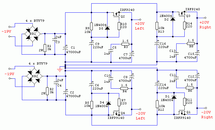
In the schematic of the CMx , it would be much more judicious that C1 = 4700-10.000uF and C7 = 22.000-47.000uF, with a 1-2.2uF MKP bypassing C7. C9 = 470uF instead of 220uF.
Above I wrote: If chokes are used, 3V must be added to this value. That is for a particular case only.
For no matter what choke, the voltage dropped on it must be added
(U = I x Re),
where I = Ibias and
Re = parasitic resistance in dc of the coil.
In the schematic of the CMx , it would be much more judicious that C1 = 4700-10.000uF and C7 = 22.000-47.000uF, with a 1-2.2uF MKP bypassing C7. C9 = 470uF instead of 220uF.
Last edited:
25v x 5A= 125VA just a toy ...you need min 300VA or better two 200VA one for sideTherefore, for 3-3,2A needed, its best to choose a trafo quoted for 4-4,5A.
A bigger one can be used, but has sense only if you find it cheaper, on SH market.
The FFT and the frequency response doesn't show any coloration. Build one and listen for yourself literally takes 15minutes a piece.
Where can you buy the boards? Or do you have the files that i can get it made?
Thanks
V
True enough. Looks simple to build.Build one and listen for yourself literally takes 15minutes a piece.
- Home
- Amplifiers
- Solid State
- Jean Hiraga Super Class A 30w Build