^^ Nice! Make sure you fuse the cathodes. That tube can fail with hard shorts that can fry a speaker in an instant.
^^ Nice! Make sure you fuse the cathodes. That tube can fail with hard shorts that can fry a speaker in an instant.
thanks, i have made provisions for that....
my main concern is that i only have 6 pcs of 6336 for matching,
not enough tubes to go by....
btw, i am sticking to the output capacitors,
with provisions for taking it out of circuit as option...
i am also making a speaker matching, 64/32 ohms to 8 ohms speakers....
Hi,
Used to have some 50 of these 6336 (A) and could not match any.
Do you put the two triodes per valve in parallel ?
Cheers, 😉
my main concern is that i only have 6 pcs of 6336 for matching,
not enough tubes to go by....
Used to have some 50 of these 6336 (A) and could not match any.
Do you put the two triodes per valve in parallel ?
Cheers, 😉
Sort of- you have to provide some current limiting to prevent current hogging. A cathode resistor does the trick. And a cathode fuse!
Do you put the two triodes per valve in parallel ?
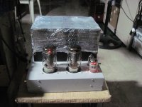
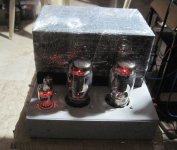
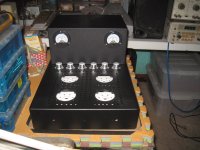
yes, individual cathodes with resistors and a fuse...btw, i now have 8 tubes and looking to get more...i have 3 6528's and also looking for more...
wired up the heaters for all tubes and power draw comes down to 160 watts.
so that 80 watt power budget for the 4 output tubes add up to 240 watts....
that is a 100 watt lower than in the 6C33 case....
so that 80 watt power budget for the 4 output tubes add up to 240 watts....
that is a 100 watt lower than in the 6C33 case....
Attachments
You will have to tell us what you were expecting to hear and what really are the differences when you get a chance to compare yours and the original
Looks good!
Regards
David
Looks good!
Regards
David
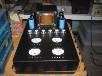
i am not even sure if this will work to my satisfaction....
originally i wanted to do a pp 6336 amp, but then i thought, less two opt's...
why not?....will keep you posted....
originally i wanted to do a pp 6336 amp, but then i thought, less two opt's...
why not?....will keep you posted....
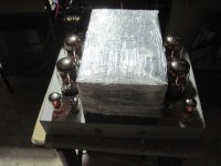
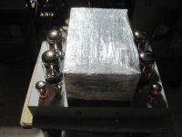
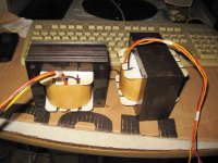
i am designing an outboard output transformer to reflect 32 ohms to 4 or 8 ohms.....
it is done, 64, 32. and 8 ohms for about 30 watts....
Attachments
Driver tube choice
And what about the EF184?
This was the driver tube of choice in the Graaf GM20 OTL which also makes use of 6C33 tubes. Used there in triode mode connected and not as a pentode.
Compared to the EF86 it has more gain and can deliver more anode current although much much lower than your recommended 6AQ5. But on the other hand amplification factor of the 6AQ5 is quite low compared to EF86/EF184. Isn't that not a disadvantage in order to reach enough output voltage swing on the grids of the 6C33 or doesn't that matter?
Your opinion?
Thank you very much
The EF86 IMO is a poor driver tube in general and its a bit mysterious to me why this tube is being used as such. Good ones are expensive, and they are not going to hold up if things go south with the power tube.
I think a better choice might be a small power pentode, since the gain is needed and the tube has to be robust. The 6AQ5 might do the job quite nicely and is far more likely to survive the voltages and currents that are required in a driver circuit!
The EF86 is a voltage amplifier that is commonly used in lower voltage settings- such as in the preamps of my Neumann microphones. I've never seen a circuit that subjects them to much voltage- the TM OTL puts them right on the edge.
So you might think about rewiring for the pin base of a common power pentode. 6AQ5s are cheap; 3 or 4 dollars on ebay.
EL84s are bit more expensive, but have the advantage of using the same 9-pin miniature socket, so might be easier to use.
And what about the EF184?
This was the driver tube of choice in the Graaf GM20 OTL which also makes use of 6C33 tubes. Used there in triode mode connected and not as a pentode.
Compared to the EF86 it has more gain and can deliver more anode current although much much lower than your recommended 6AQ5. But on the other hand amplification factor of the 6AQ5 is quite low compared to EF86/EF184. Isn't that not a disadvantage in order to reach enough output voltage swing on the grids of the 6C33 or doesn't that matter?
Your opinion?
Thank you very much
Burn in
Ok and thanks for the tip.
So if B+ has already been applied once to the tube for instance for a short functional test does it make then no sense to do this?
And do all other connections i.e. anode, grid and cathode of the 6C33 need to remain open respectively not connected during this time frame?
Thank you very much.
I recommend 4 days and nights in Standby for a 6C33. This can double the life of the tube.
This only applies if B+ has not been applied to the power tube.
Ok and thanks for the tip.
So if B+ has already been applied once to the tube for instance for a short functional test does it make then no sense to do this?
And do all other connections i.e. anode, grid and cathode of the 6C33 need to remain open respectively not connected during this time frame?
Thank you very much.
Hi AJT!
Greets:
Tyimo
How is the sound with the OPT compared to the OTL version???????it is done, 64, 32. and 8 ohms for about 30 watts....
Greets:
Tyimo
And what about the EF184?
This was the driver tube of choice in the Graaf GM20 OTL which also makes use of 6C33 tubes. Used there in triode mode connected and not as a pentode.
Compared to the EF86 it has more gain and can deliver more anode current although much much lower than your recommended 6AQ5. But on the other hand amplification factor of the 6AQ5 is quite low compared to EF86/EF184. Isn't that not a disadvantage in order to reach enough output voltage swing on the grids of the 6C33 or doesn't that matter?
Your opinion?
Thank you very much
The difference of mu of the tube isn't going to affect things much. However, if the power tube arcs it can damage its driver tube and the 6AQ5 is common and inexpensive and also is far more likely to survive the arcing event.
Ok and thanks for the tip.
So if B+ has already been applied once to the tube for instance for a short functional test does it make then no sense to do this?
And do all other connections i.e. anode, grid and cathode of the 6C33 need to remain open respectively not connected during this time frame?
Thank you very much.
If B+ gets applied the preconditioning is over. In preconditioning jigs the other elements of the tube are traditionally tied to one side of the filament circuit.
i am looking at 12by7, 12hg7, 12gn7, 12hl7
and the other video pentodes....
the thing with drivers is the plate ratings,
a pentode that can do 300 volts plate
as voltage amplifier is it imho....
the russian 6P15P is also cheap...
and the other video pentodes....
the thing with drivers is the plate ratings,
a pentode that can do 300 volts plate
as voltage amplifier is it imho....
the russian 6P15P is also cheap...
Hi AJT!
How is the sound with the OPT compared to the OTL version???????
Greets:
Tyimo
not yet tried as i still have a lot of other things on my plate, will update soon...
Driver tube damage due to arcing
Ok, I can imagine that a 6AQ5 is a more robust tube when it comes to arcing of the 6C33 but I wonder if part of the problem for this in case of the Tim Mellow design is also due to it's circuit topology.
In this design the anode of the EF86 is directly connected with the grid of the 6C33 with nothing in between as opposed to the Graaf GM20 schematic where there is a 220 Ohm grid stopper and a 1uf capacitor bypassed with a 470k resistor in series between the EF184 anode and the grid of the 6C33.
As such I could imagine that the Graaf GM20 EF184 driver tube then is prone to a much lesser degree to damage in case of arcing if at all.
Is that right or would you disagree with my assumption.
Thanks
The difference of mu of the tube isn't going to affect things much. However, if the power tube arcs it can damage its driver tube and the 6AQ5 is common and inexpensive and also is far more likely to survive the arcing event.
Ok, I can imagine that a 6AQ5 is a more robust tube when it comes to arcing of the 6C33 but I wonder if part of the problem for this in case of the Tim Mellow design is also due to it's circuit topology.
In this design the anode of the EF86 is directly connected with the grid of the 6C33 with nothing in between as opposed to the Graaf GM20 schematic where there is a 220 Ohm grid stopper and a 1uf capacitor bypassed with a 470k resistor in series between the EF184 anode and the grid of the 6C33.
As such I could imagine that the Graaf GM20 EF184 driver tube then is prone to a much lesser degree to damage in case of arcing if at all.
Is that right or would you disagree with my assumption.
Thanks
^^ I think a grid stopper is an extremely good idea and something to add to the design of the amp!
Such a device would reduce the chance of damage to the driver tube during an arcing event. 1K might do it- but it should be a 3-watt device...
Such a device would reduce the chance of damage to the driver tube during an arcing event. 1K might do it- but it should be a 3-watt device...


- Home
- Amplifiers
- Tubes / Valves
- New Tim Mellows OTL project