Clearly I am not googling right. I'll try harder, but may have to ask for a pointer if I am still stuck. Currently the linear app notes I have found make most sense, but I've only just realised how much I need to still learn in this area. All good 🙂
Wayne has a couple of designs near SOTA with measurements with real cartridges and various devicesNow I'm just confused over the best way to do a FET/opamp hybrid for when I need lowest noise.
Pro Audio Design Forum • View topic - A Low Noise Balanced In Moving Coil Preamp Using the ZTX851
Pro Audio Design Forum • View topic - Flat Phono Preamp Based on John's P10 and 2SK389
These were done for master monitoring and digital declicking & RIAA but also include full accurate analogue RIAA EQ.
My take on your requirement is Guru Wurcer's AD624 can replace the input INA for the MM version.
You don't have to build it all .. just the bits you need.
I pontificate at various points in these huge threads on digital EQ
IIRC, Wayne lists the digital RIAA EQs he has found to be accurate.
Much reading to be done 🙂. Just to be clear this was musing about future stuff. I figure it's better to understand one topology well than many poorly. As well as a couple of MMs I do have 2 MCs, the lowest of which is 0.25mV. Well would be churlish not to try a transimpedance amplifier on that as well. I will end up with a spare twisted pair unit eventually which should 'do the job' but musing on 'how low can you go' is intriguing.
I am also hoping that, if we ever manage to fully seperate electrical and mechanical resonances successfully for MM we should check if MC has the same mech issues. This could of course take a while.
I am also hoping that, if we ever manage to fully seperate electrical and mechanical resonances successfully for MM we should check if MC has the same mech issues. This could of course take a while.
Thank you George. I think the dominant characteristic is the sloping hf loss, which AFAIK is typical of the M97e. See these measurements which confirm, and contrast them to, say, an Ortofon 2M Blue which generator is apparently non-lossy in the audioband IME Cartridge testsPlaying test records
Aurak V3 (OPA2134, NE5532)
vs
Hagerman Bugle (3xOPA2134)
SHURE M97xE on Kenwood KD-3100 with a typical S tonearm.
Cartridge to preamplifier wiring:100pF
The Hi-FI News 002 Test LP (HFN)
Side 1 Band 3 (pink noise)
Side 2 Band 7 (full range freq sweep)
The Ultimate Analog Test LP (UAT)
Side 1 Track 6 (1KHz-20KHz stepped freq sweep)
Side 2 Track 2 (pink noise)
All 24b/96KHz recordings level matched at 1KHz to +/- 0.1dB
George
So it seems, for better or worse, you have chosen a M97e cartridge with an intrinsically lossy generator, perhaps, or at least a characteristically sloping f response. Which, academically I find very interesting as to why it might be so, but isn't necessarily characteristic of all MM/MI carts, especially Ortofons/AT types IME.
Dlaloum on ZevAudio posts measurements of the Shure 1000e/ N97e which is an interesting reference point, in which he attempted to deduce the mechanical resonance of the N97e and shows a plot here https://sites.google.com/site/zevaudio/turt/cartridge-comparison-list/shure-1000e
George, your plots of the Aurak versus Hagerman preamps are interesting, and perhaps hint at Aurak revealing aspects of the mechanical resonance, but the discontinuity at 20kHz I don't understand ?
Thanks again.
LD
Playing test records
Aurak V3 (OPA2134, NE5532)
vs
Hagerman Bugle (3xOPA2134)
SHURE M97xE on Kenwood KD-3100 with a typical S tonearm.
Cartridge to preamplifier wiring:100pF
The Hi-FI News 002 Test LP (HFN)
Side 1 Band 3 (pink noise)
Side 2 Band 7 (full range freq sweep)
The Ultimate Analog Test LP (UAT)
Side 1 Track 6 (1KHz-20KHz stepped freq sweep)
Side 2 Track 2 (pink noise)
All 24b/96KHz recordings level matched at 1KHz to +/- 0.1dB
George
George,
I have a problem to understand what I see in your images.
Could you please explain what you have done and how.
Pink noise means an equal amount of energy in each octave, so when recording this wideband signal with an FFT with a fixed filter width, you will see a 3dB/oct or 10dB/decade downwards slope, which can be seen in your recording from 100Hz to 10Khz.So far so good.
What I do not understand is why the frequency sweep is not flat over a large portion of the FR. And I'm also curious to know how you were able to make this picture.
The stepped frequency image is already much better in showing the FR, but like the pink noise this is probably not a sweep but a continuous signal with all multiples of 1Khz playing at the same time.
Last but not least, I'm puzzled by the fact that the Virtual input Aurak hardly makes a difference to a straightforward 47K/100pF input Phono Amp, at least not in the way I was expecting.
Maybe a silly question, but are you 100% sure that your cart is working properly and that you assumed the correct Lcart and Rcart for the Aurak?
Hans
Last edited:
Dlaloum on ZevAudio posts measurements of the Shure 1000e/ N97e which is an interesting reference point, in which he attempted to deduce the mechanical resonance of the N97e and shows a plot here https://sites.google.com/site/zevaudio/turt/cartridge-comparison-list/shure-1000e
George, your plots of the Aurak versus Hagerman preamps are interesting, and perhaps hint at Aurak revealing aspects of the mechanical resonance, but the discontinuity at 20kHz I don't understand ?
Thanks again.
LD
Why do they choose linear phase equalization?
Why do they choose linear phase equalization?
They describe their thinking here: https://sites.google.com/site/zevaudio/turt/digital-equalisation
When I put the results from the multiple frequencies recording in a graph, I get the image below from 1Khz to 32Khz.
FR seems rather disastrous for both preamps.
Hans

FR seems rather disastrous for both preamps.
Hans
Or the test records have a problem...
When pink noise shows an almost straight line from 100Hz to 10Khz with a 10dB/decade slope, I have no direct reasons to mistrust the testrecord.
At least from the same 100Hz to 10Khz FR should therefore be flat with a sweep.
But the sweep shows almost 10dB difference between 1Khz and 10Khz, as if it were pink noise too !
I would not suspect the testrecord as the first in line having a problem, although maybe the wrong track could have been selected.
And I have no clue how the FR plot was registered in the first place and put into a curve.
Hans
They describe their thinking here: https://sites.google.com/site/zevaudio/turt/digital-equalisation
Most of the mechanical anomalies are causing minimum phase frequency response deviations (I see Lucky already gave them his input). 🙂
BTW I saw today an add for a flat phono pre-amp so "You could hear the music as the recording engineer intended without added equalization".😕
Which, academically I find very interesting as to why it might be so, but isn't necessarily characteristic of all MM/MI carts, especially Ortofons/AT types IME.
Hi Lucky
The real reason Shure M97xE entered the test scene was because Bill asked for some tests on it. It isn't used in an attempt for generalizing.
That said, in terms of frequency response, the electrical motor of this cartridge is I would say mediocre (*).
It’s strong point is the moving assembly. The cantilever compared to those of the cheap cartridges, is like night and day. The diamond tip is also fine. Shure from the start worked hard on excelling in trackability.
(*) and I can’t understand why they insist in using that design.
but the discontinuity at 20kHz I don't understand ?
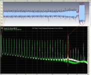
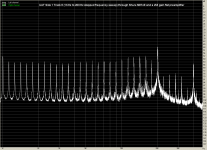
I think you mean the high peak at 20KHz of the stepped freq sweep.
See why it happens in the first attachment:
The 1KHz high peak is due to longer section in that vinyl track.
The 20KHz high peak is due to longer section in the vinyl track in combination with much higher level of vinyl cut.
(FFT was not on their mind as an evaluation tool when they cut these test tracks, only Voltmeter).
Could you please explain what you have done and how.
Hi Hans
What did I do:
The plots you saw, were the result of FFT on the recordings at the output of the RIAA preamplifiers.
The stepped frequency image is already much better in showing the FR, but like the pink noise this is probably not a sweep but a continuous signal with all multiples of 1Khz playing at the same time.
UAT Side 1 Track 6 is discrete freq steps, not continuous freq sweep (confirmed through listening).
You can see continuous freq sweep in HFN Side 2 Band 7.
Using the same TT, arm, cable and M97xE cartridge, I recorded the same tracks, this time using a flat preamplifier (cartridge loading is again 47K). See second to fifth attachments for the FFTs of the flat recordings (excuse the 50Hz peak).
Has anyone made recordings using any of these two test records? If yes, please show results here. (**)
but are you 100% sure that your cart is working properly
I guess yes. The general shape of the FFTs looks familiar to me.
I’ll try to find recordings from the same tracks done with my (ex) DL-103 and compare the FFTs.
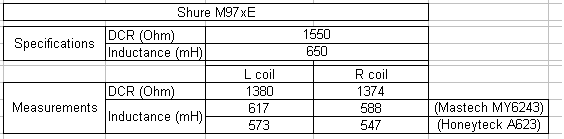
and that you assumed the correct Lcart and Rcart for the Aurak?
I measured the coil inductance with two LC meters and the DC resistance with two multimeters. See the last attachment.
(**) There is some critique over the flatness of HFN pink noise here
How to plot a cartridge frequency response | Steve Hoffman Music Forums
George
Attachments
-
 (0) UAT S1 T6.PNG875.2 KB · Views: 286
 -
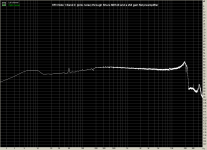 (1) HFN S1 B3 flat through Shure M97xE.png31.9 KB · Views: 269
 -
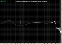 (2) UAT S2 T2 flat through Shure M97xE.png32.5 KB · Views: 262
 -
 (3) HFN S2 B7 flat through Shure M97xE.png35.7 KB · Views: 264
 -
 (4) UAT S1 T6 flat through Shure M97xE.png47.4 KB · Views: 257
 -
 (5) Shure M97 measurements.PNG6 KB · Views: 115
Search me, Scott........IIRC I did point out concerns at the time. Perhaps some confusion re the terms involved, but just guessing........?Why do they choose linear phase equalization?
LD
George,
I'm a bit lost. When you do an FFT from a frequency sweep, result depends on how long or how much energy was accumulated at a certain frequency.
Since this is not the primary task of a sweep on a test disc, results will be very inaccurate.
Playing pink noise over an flat amp is just as inaccurate because noise was recorded with riaa correction..
Much better is to use a test disk with many single frequencies and use a voltmeter.
Alternatively is it possible to mathematically tilt the pink noise curve by +10dB / decade, this will be much more reliable than the two other methods that you used.
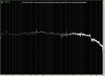
I have made a quick correction of the pink noise curve from the Aurak, taken with HFN 1 track 3.
I still don't understand that at 20Khz FR almost stops. Has this to do with the limited BW of the pink noise, or may be with your A/D conversion ??
Anyhow, the corrected curve looks like a decent frequency curve.
Hans

I'm a bit lost. When you do an FFT from a frequency sweep, result depends on how long or how much energy was accumulated at a certain frequency.
Since this is not the primary task of a sweep on a test disc, results will be very inaccurate.
Playing pink noise over an flat amp is just as inaccurate because noise was recorded with riaa correction..
Much better is to use a test disk with many single frequencies and use a voltmeter.
Alternatively is it possible to mathematically tilt the pink noise curve by +10dB / decade, this will be much more reliable than the two other methods that you used.
I have made a quick correction of the pink noise curve from the Aurak, taken with HFN 1 track 3.
I still don't understand that at 20Khz FR almost stops. Has this to do with the limited BW of the pink noise, or may be with your A/D conversion ??
Anyhow, the corrected curve looks like a decent frequency curve.
Hans
Search me, Scott........IIRC I did point out concerns at the time. Perhaps some confusion re the terms involved, but just guessing........?
LD
Some articles use the terms linear and non-linear phase to further confuse the issue.
The 2dB shoulder at 10Khz that was visible when connecting the Cart in series with a generator, could be simulated as a model by dividing Lcart in 2 parts thereby adding a resistor in par. to one part.
LD already suggested that when the Cart itself was used as a generator that this would result in a dip because of the losses caused by the resistor and that is more or less exactly what can be seen in the FR generated from the tilted pink noise curve two postings above this one
Hans
LD already suggested that when the Cart itself was used as a generator that this would result in a dip because of the losses caused by the resistor and that is more or less exactly what can be seen in the FR generated from the tilted pink noise curve two postings above this one
Hans
Presumably due to the intrinsic cartridge FR response.FR seems rather disastrous for both preamps.
Indeed. You are always so very generous, George, stronger terms might apply on the face of it 😉That said, in terms of frequency response, the electrical motor of this cartridge is I would say mediocre (*).
(*) and I can’t understand why they insist in using that design.
In a cartridge coil, flux change is entirely the result of generator motion, and load doesn't change this for the same reasons flux doesn't change in a transformer core as a result of secondary load, despite that being counter-intuitive.
Coil/core losses should simply follow flux change, so in principle aren't affected by coil load. This is why the Hagerman conventional loading preamp shows similar audioband results to the Aurak preamp, even in the event of a prima facie lossy generator, I think.
LD
Last edited:
Yes, of course ! I thought it was already corrected.I have made a quick correction of the pink noise curve from the Aurak, taken with HFN 1 track 3.
LD
I still feel a bit guilty over having asked but eternally grateful for the data 🙂Hi Lucky
The real reason Shure M97xE entered the test scene was because Bill asked for some tests on it. It isn't used in an attempt for generalizing.
George
- Home
- Source & Line
- Analogue Source
- mechanical resonance in MMs