Here is the proof.
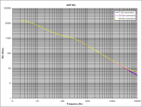
The Anti Riaa Filter followed by an exact inverse Laplace transformation.
Deviation at 300Khz is -1dB.
Hans
View attachment 610912
You need to specify the source impedance, the picture does not. There are lots of 600 Ohm generators out there.
Last edited:
You need to specify the source impedance, the picture does not. There are lots of 600 Ohm generators out there.
Scott,
As you can see in the circuit diagram, I used a source impedance of 50 Ohm.
And as far as I know, this is exactly the source impedance of Georges generator.
Hans
I am reading the equation with e^2 as meaning the voltage squared. It's just the usual "Power = Voltage^2 / R " formula.
Thank you Mark and apologies. A serious mistake from my part.
A quadratic function is not an exponential function!
Back to elementary school.
Scott,
As you can see in the circuit diagram, I used a source impedance of 50 Ohm.
And as far as I know, this is exactly the source impedance of Georges generator.
Yes. My generator is 50 Ohm.
I’ve simulated the circuit myself. It is perfect.
But the issue is with the real circuit. That’s why I asked if someone has measured his anti-RIAA filter at higher frequencies.
I will investigate a bit more.
George
It may not come as a surprise, but yes I have this Anti Riaa Filter (ARF) equiped with 1% polypropylene caps and 0.1% film resistors.Yes. My generator is 50 Ohm.
I’ve simulated the circuit myself. It is perfect.
But the issue is with the real circuit. That’s why I asked if someone has measured his anti-RIAA filter at higher frequencies.
I will investigate a bit more.
George
My MC Preamp is supposed to be flat within 0.1 dB up to 100Khz.
And what I measure with this ARF is within 0.25 dB up to 100Khz. I cant remember the response above 100 KHz.
Hans
Thank you Hans. This too hints to excessive drive requirements for my MM case (you don't have that problem, as you are asking some 20dB less drive from your generator)It may not come as a surprise, but yes I have this Anti Riaa Filter (ARF) equipped with 1% polypropylene caps and 0.1% film resistors.
My MC Preamp is supposed to be flat within 0.1 dB up to 100Khz.
And what I measure with this ARF is within 0.25 dB up to 100Khz. I cant remember the response above 100 KHz.
Hans
I am going to torture-test my generator because I think the problem is there, actually what Scott said.
what you show can't rise forever the 5 Ohms and the generator resistance limits the rise.
George
Thank you Hans. This too hints to excessive drive requirements for my MM case (you don't have that problem, as you are asking some 20dB less drive from your generator)
I am going to torture-test my generator because I think the problem is there, actually what Scott said.
George
You could change the 5 Ohm to 20 Ohm. The FR drops from -1dB@5Ohm to -1.5dB@20Ohm at 300 Khz, no big deal, and you have 12dB more output.
Hans
George,
Here is the very slight difference in FR when going from 5 Ohm to 20 Ohm.
Gain of course has been increased by 12 dB.
Hope this suits your application better, and it is very easy to compensate the outcome with the drop in FR at 300 Khz.
Hans

Here is the very slight difference in FR when going from 5 Ohm to 20 Ohm.
Gain of course has been increased by 12 dB.
Hope this suits your application better, and it is very easy to compensate the outcome with the drop in FR at 300 Khz.
Hans
Thank you Hans.
I spent some hours turning the knobs, watching the scope screen, reading the meters and writing down the numbers.
The discrepancy is indeed due to the loading of the generator by the ARF.
So, the signal at the input of the ARF drops, which I hadn’t taken into account when I filled the data for the plots in post #557.
I hadn’t noticed it because it is not that straightforward like clipping or slew limiting as it happens with a low Ohm resistor directly at the output of the generator.
The ARF makes the signal across it’s input to drop a bit above about 100KHz, the amount of drop affected by the signal level.
I had to plot the Rin of the filter for to understand what is going on.
Spot measurement at 10 frequencies with the ARF as is (with the 5 Ohm terminating resistor). Then I simulated the same measurements. Test and simulation data coincide.
The ARF Rin plots for the case of 20 Ohm and 50 Ohm terminating resistor are made out of simulated measurements entirely (no verification through actual measurements).
George
Attachments
I meant the stuff used inI don't know what you mean by dedicated instructions, I consider multiply and add pretty general purpose. The FIR section of my article was more like "Muntzing" the maths.
FFTW Home Page
ConvolverVST
BruteFIR
These all came out when I'd disappeared into the bush so I don't know much about them except that they exploit parallelism for more efficient FFTs & keep stuff within CPU caches .. especially 2D FFTs for video & image processing.
You are thinking of straight Bi-Linear Transform to dream up IIRs from s=jw functions.How did you handle the frequency warping in the upper octaves? The equations start including transcendentals and do not yield to closed form solution.
There's plenty of formal textbook stuff on how to do frequency warping on 'classic' filter' shapes .. but eg I think the 75us pole in RIAA can be straight Bi-Linear transform.
The Help Files with the DSP toolkit for MATLAB are a very convenient reference to all this hi-falutin stuff though you need to take their pronouncements of which method is good / bad / impossible with large pinches of salt. Sadly, I no longer have access to a pukka copy of MATLAB with these Help Files 😡
Simple Arbitrary IIRs (SAI) is really an Impulse Invariant method, so gets the HF stuff nicely accurate provided you are not trying to do zillion dB/8ve anti-aliasing filters (one of two applications I think appropriate for EVIL FIRs)
At lower frequencies, simple Bi-Quads are subject to noise and sensitivity to coeffs
[30] http://www.analog-eetimes.com/en/which-filters-are-noisier-analog-or-digital-part-2.html?cmp_id=71&news_id=222902322&vID=35
I think 4th order HiPass at 20Hz (fs 44.1kHz) is still OK with just the accumulator made double (at least for accuracy) but a 2nd order Bi-Quad (one parametric) at 1Hz needs stuff like
[31] Goodall & Donoghue , “Very high sample rate filters using the operator” IEE Proc. vol140 no3 jun93
[32] Middleton & Goodwin, “Digital Control and Estimation – a unified approach” Prentice Hall ISBN 0-13-211793-3
The reason for wanting arbitrary IIRs is that the various filters (including EVIL FIRs) using different methods for various frequency ranges, can be concatenated into one large arbitrary IIR
Excuse me for being brusque but this is a HUGE topic. I pontificate further in SAI
___________________________________
Dammit! I was hoping it was Jan releasing your Linear Audio article for free 😡EDIT - Good, he has it up for free http://alumni.media.mit.edu/~adamb/docs/ConvolutionPaper.pdf
Excuse me for being brusque but this is a HUGE topic.
Ricardo, there is a relevant thread here:
http://www.diyaudio.com/forums/analogue-source/298896-digitizing-vinyl.html#post4876870
I pontificate further in SAI
Link?
George
Indeed.You could change the 5 Ohm to 20 Ohm. The FR drops from -1dB@5Ohm to -1.5dB@20Ohm at 300 Khz, no big deal, and you have 12dB more output.
I've lost track of the absolute level@1kHz being applied to the cartridge in George's most recent tests. I think the RIAA correction network is a very good thing, BTW.
Thank you George for doing these tests. Would re-runs with level 5mV@1kHz and 0.5mV@1kHz be possible please? I'm interested in exploring the nature of coil losses -v- level in this configuration.
LD
Sorry George. I was just answering Guru Wurcer 😱Ricardo, there is a relevant thread here:
http://www.diyaudio.com/forums/analogue-source/298896-digitizing-vinyl.html#post4876870
Simple Arbitrary IIRsLink?
George,
I'm not exactly sure in what way your generator is misbehaving, but the simplest way to check is to measure the input voltage going into the ARF.
There is however a possibility that your generator doesn't like variable loads and prefers to be permanently loaded by 50 Ohm.
I have simulated both situations, left image is the input voltage to your ARF when additionally loading your generator with 50 Ohm, this is in parallel to the ARF.
The right image displays the input voltage to your ARF without this extra 50 Ohm load.
Green line in both cases is with 5 Ohm and Blue shows the 20 Ohm load below the ARF.
What ever deviation from these curves can be compensated for in your final plot.
Hans
Sorry Bill. As I said, I was just answering Guru Wurcer.billshurv said:Is there a translator for Ricardo somewhere or is this some form of enrichment play?
George, I've just clicked on all 33 pages of Digitising Vinyl. I can't claim to have read every post but I now understand Guru Wurcer's caveats about 'frequency warping' in bi-quads. I think all my contributions to that subject are already on Wayne Kirkwood's 2 threads in his www.proaudiodesign.com
The relevance of "Simple Arbitrary IIRs" to this thread is that once you've measured the response with your Test Record and whatever 'flat' (or not) preamp you prefer, you need some way of dreaming up a digital filter to correct whatever response you see including adding RIAA ... either full or partial.
IMHO, SAI is the best way of doing this for real. Roughly speaking, using this method for IIRs will give similar 'accuracy' to an EVIL FIR 5-10x larger .. with some caveats about the advantage of large FFTs at these respective sizes for computational efficiency.
Even if I was designing FIRs for this, I would use SAI to design IIRs and then convert them into big EVIL FIRs. I've done this for Prof Angelo Farina who prefers FIRs.
I'm not sure agonising over 0.1dB RIAA accuracy is justified when you also need to correct cartridge, loading, mechanical resonances & other effects.
Ah fairy nuff. I am stuck with IIRs so am not worrying about FIRs. I have listened to George's FIR vs IIR samples and no 'night and day' differences.
It's never worth agonising over the last 0.1dB but as the purpose of this thread is to look at fixing the loading problem and then measuring the residual mechanical issues that we can correct we do stand a fine chance of getting better performance that most at the end. This ignores that many people actually show a preference for a messed up FR and 'roll cartridges' to that end. nowt as queer as folk.
I'm not sure agonising over 0.1dB RIAA accuracy is justified when you also need to correct cartridge, loading, mechanical resonances & other effects
It's never worth agonising over the last 0.1dB but as the purpose of this thread is to look at fixing the loading problem and then measuring the residual mechanical issues that we can correct we do stand a fine chance of getting better performance that most at the end. This ignores that many people actually show a preference for a messed up FR and 'roll cartridges' to that end. nowt as queer as folk.
The reason for wanting arbitrary IIRs is that the various filters (including EVIL FIRs) using different methods for various frequency ranges, can be concatenated into one large arbitrary IIR
Excuse me for being brusque but this is a HUGE topic. I pontificate further in SAI
___________________________________
Dammit! I was hoping it was Jan releasing your Linear Audio article for free 😡
Thank you Richard for the explanations. Once you invoke big maths the audience among the average DIY community shrinks to nil. My article was geared to help the average DIY'er use, if necessary, what is out there for free or on the cheap do essentially as good a job as possible. I was only addressing RIAA with as little theoretical math as possible, that meant simple bi-quads. Bob Orban also had his own technique for doing RIAA with polynomials in z but once past bi-quad level you are programming it yourself. Honestly I feel that brings the audience to virtually zero. My FIR trick works for RIAA and some other things but I offered it with no theoretical background at all.
My link was only to show that the convolution of your evil FIR with the input can be done with no latency.
I'll see if Bob Adams can save me the $33. 😀
EDIT - Richard could you do just the three time constant SAI RIAA and show us the results, I'm curious to compare at the frequency extremes?
Last edited:
Scott,
As you can see in the circuit diagram, I used a source impedance of 50 Ohm.
And as far as I know, this is exactly the source impedance of Georges generator.
Hans
George's picture didn't make that clear but at these impedance levels and frequencies only generator loading could make that much difference.
I think all my contributions to that subject are already on Wayne Kirkwood's 2 threads in his www.proaudiodesign.com
I didn't find any threads there.
Also, I am not going to spend $33 to find out if you wrote something that may or may not be useful to me.
In addition, it would be interesting to hear why you refer to FIRs as evil. They seem to have their uses.
Ah, now it all makes sense. Although for my application rolling cart eq, crossover and speaker eq into amorphous IIR blocks would end up confusing me totally.
But then again I am seriously considering getting a Behringer for messing about with settings as its quick and easy and has lots of pre-sets.
But then again I am seriously considering getting a Behringer for messing about with settings as its quick and easy and has lots of pre-sets.
- Home
- Source & Line
- Analogue Source
- mechanical resonance in MMs