Disconnected one side of R1, R1A, R101 & R101A.
With multimeter on V setting (2000mV) i am getting 4 zero readings
With it on ohm setting (200) i am getting four 0.6/0.7 readings.
With multimeter on V setting (2000mV) i am getting 4 zero readings
With it on ohm setting (200) i am getting four 0.6/0.7 readings.
Why did you disconnect them? Thats not what we said to do. You want to measure the voltage drop over them with the POWER on. This will tell you the bias current with ohms law V=IR, or in this case, I = V/R.
Naturally you will get no voltage reading if they are not in circuit and no power is applied.
Naturally you will get no voltage reading if they are not in circuit and no power is applied.
@Mooly, this particular Delta 290P is actually the Arcam Alpha 9 circuit. Look at the schematic for that. It has an auto-bias scheme where the voltage across R1/R1A is sensed and compared with a fixed threshold voltage by one half of a LM393 comparator. This then adjusts the bias current by adjusting the LTP tail current 😵
To be honest I cant help feeling Arcam pulled a bit of a switcheroo here. The Alpha 9 is nothing like the Delta 290 apart from the fact it uses the same output MOSFETs.
To be honest I cant help feeling Arcam pulled a bit of a switcheroo here. The Alpha 9 is nothing like the Delta 290 apart from the fact it uses the same output MOSFETs.
Also, the voltage across R1/R1A and R101/R101A is what is used to sense the VI protection. So there is a fault somewhere around here which is what is causing the distortion and the protection to trip.
@PeterMac63, you are going to need to do a lot of tests now with the power on to hunt this down. Obviously this means you need to be very careful, one slip of the probe will cause major damage. You might be best getting some hook clip leads like these:
4mm Probe Clip Test Cables | Maplin
4mm Probe Clip Test Cables | Maplin
Hi. Yes, aware of that.
First results. 200mV setting. Power on. No speakers switched.
R101 and R101A give 0.1
R1 and R1A give 7.0
Reading the board, the latter is left channel.
First results. 200mV setting. Power on. No speakers switched.
R101 and R101A give 0.1
R1 and R1A give 7.0
Reading the board, the latter is left channel.
@Mooly, this particular Delta 290P is actually the Arcam Alpha 9 circuit. Look at the schematic for that. It has an auto-bias scheme where the voltage across R1/R1A is sensed and compared with a fixed threshold voltage by one half of a LM393 comparator. This then adjusts the bias current by adjusting the LTP tail current 😵
To be honest I cant help feeling Arcam pulled a bit of a switcheroo here. The Alpha 9 is nothing like the Delta 290 apart from the fact it uses the same output MOSFETs.
Thanks jaycee 🙂 yes it is totally different. I wonder who dreamed that circuit up 😀
You can still check the bias by measuring across R1 and R101. Anything over a couple of millivolts will be enough to prevent audible crossover distortion.
R101 and R101A give 0.1
R1 and R1A give 7.0
Reading the board, the latter is left channel.
So are we saying one channel has no bias current flowing ?
You could very carefully measure the voltage across R17 and R117 to compare. The voltage across that resistor determines at what point the output stage will conduct.
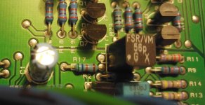
Still looking for R117!!
I see R17.
R121 looks same as R17 and in similar position relative to other mirrored components. The board isn't symmetrical.
I see R17.
R121 looks same as R17 and in similar position relative to other mirrored components. The board isn't symmetrical.
Last edited:
OK, I think R121 is actually the number for the capacitor to the right and R117 does not have a number or its hidden somewhere under something else. Check out 2 pics.
What setting am I checking these at.
What setting am I checking these at.
Attachments

Last edited:
7mV is right, and in line with what the service manual says (6-7mV giving ~60mA bias through the outputs)
0.1mV is definitely not. There is something wrong on that channel. Parts prefixed with 100 ie R101 means the right-hand channel, according to the service manual.
0.1mV is definitely not. There is something wrong on that channel. Parts prefixed with 100 ie R101 means the right-hand channel, according to the service manual.
OK, shutting up for today, but Mooly did say "You could very carefully measure the voltage across R17 and R117 to compare. The voltage across that resistor determines at what point the output stage will conduct.
I will do that once I am sure what setting to have the multi-meter at.
Cheers guys!
I will do that once I am sure what setting to have the multi-meter at.
Cheers guys!
R17 connects the collectors of Q8 and Q7 together.. those are the terminals labelled "C" on the transistors nearby.
R117 does the same for Q108 and Q107 in the right hand channel.
R117 does the same for Q108 and Q107 in the right hand channel.
Yes, it was just not labelled so I was unsure but I am now certain that is it in photo 2 and that the misleading label actually refers to the one to the right.
Green /blue/orange/brown same as R17
Green /blue/orange/brown same as R17
When you measure voltage across a resistor, typically you should start at millivolts. If the meter shows you "over range" then you can advance up.
When you're measuring voltages across resistances like this, what you are actually doing is measuring current flowing through the resistor. As Ohms Law says, voltage (volts) = resistance (ohms) times current (amps). So if you know a voltage and a resistance, you can find current.
When you're measuring voltages across resistances like this, what you are actually doing is measuring current flowing through the resistor. As Ohms Law says, voltage (volts) = resistance (ohms) times current (amps). So if you know a voltage and a resistance, you can find current.
Yes, it was just not labelled so I was unsure but I am now certain that is it in photo 2 and that the misleading label actually refers to the one to the right.
Yeah, silkscreen markings can be a bitch 😉
Interesting. That seems to move the problem away from the output stage then. Zero volts is the reason for the distortion and no bias.
The original problem of the bridge rectifier was a one off definite fault and should have caused no repercussions down the line.
We fault find this issue as we would any other but its also worth you looking back over any work you may have done, any parts replaced and so on. Check for solder splashes as well.
Make sure the -15 volts is present as shown on the diagram.
This auto bias thing complicates things. I don't know what sort of range that thing has and whether it could fully cut the bias. The voltage across C120/C107 determine the operating point. Might be worth comparing between channels the voltage across those.
Also, faults like have the potential to turn into destructive ones and so I might be inclined to go back to the bulb tester while working on it.
- Status
- Not open for further replies.
- Home
- Amplifiers
- Solid State
- Arcam Delta 290P keeps blowing fuse