Very small PCB based on Yorkville Amps.
Dear Mr. Apex,
what would be the effect of replacement C1(220nF) by 1uF? C1 if I am not mistaken, is too low a valueand will degrade low frequency performance. TI recommends 10uF coupling capacitor.
regards
prasi
Is this thread dead? Nobody appears to reply to it any more.Dear Mr. Apex,
what would be the effect of replacement C1(220nF) by 1uF? C1 if I am not mistaken, is too low a valueand will degrade low frequency performance. TI recommends 10uF coupling capacitor.
regards
prasi
Reg
Prasi
He could be sleeping or at work. He replies. However you can use any larger size you like. 10uf or even 1uf would be fine.
He could be sleeping or at work. He replies. However you can use any larger size you like. 10uf or even 1uf would be fine.
Hi udailey.. thanks for ur reply. What I would like to understand is that whether a larger value of capacitor would improve low frequency response. Also any other way to boost bass 20-70 hz.
Regards
Praai
Yes. Larger values allow lower frequency -3db points. The bipolar cap in the feedback loop that goes to ground is important in this situation as well. Read lm3886 datasheet and it shows the formula for figuring out the right values for lower frequencies.
I'm planning on building this circuit and ordering parts from Mouser but the cost is adding up quickly! Could someone let me know if this parts list is overkill, and if I could save money by using lower quality components anywhere? The component numbers are in reference to the schematic on page 1, but also include the upgrades mentioned by others in this thread.
Basically I've used metal film resistors and the highest quality polypropylene and electrolytic caps I could find where ever possible, but I expect some components don't affect the sound quality (C5, R5, C6, C7, R2, R3, R4 ??)
Here's the BOM on Google Docs:
https://docs.google.com/spreadsheets/d/1NIjnpftJUmgYAPfuft6lqWV128HQln37YLxrXch4qHY/edit?usp=sharing
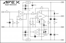
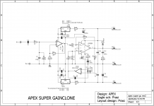
APEX Super Gainclone
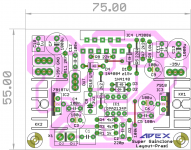
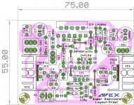
Mr. Mile Here is the layout for Super Gainclone. Is it ok?
regards
Prasi
Attachments

Mr. Mile Here is the layout for Super Gainclone. Is it ok?
regards
Prasi
Nice work but one connection missing.
Regards
Attachments
Nice work but one connection missing.
Regards
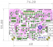
Corrected, also had to increase the size a bit for 13mm caps for C7 and C13. Earlier I had 10mm dia capacitors.
regards
Prasi
Attachments
Last edited:
Corrected, also had to increase the size a bit for 13mm caps for C7 and C13. Earlier I had 10mm dia capacitors.
regards
Prasi
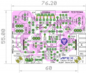
One more correction, 56R in series with regulators.
Attachments

Last edited:

One more correction, 56R in series with regulators.
Mr.Mile,
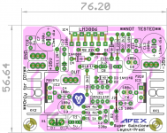
added 56R resistors on regs and also managed to loose one jumper. is it perfect now?
reg
Prasi
Attachments
Last edited:
Mr.Mile,
added 56R resistors on regs and also managed to loose one jumper. is it perfect now?
reg
Prasi
Yes it is perfect, thank you.
Regards
Yes it is perfect, thank you.
Regards
Thanks Mr. Mile.
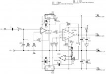
Here are the schematic, stuffing guide, pdf's and gerbers for anyone willing to try🙂.
reg
Prasi
Attachments
Last edited:
Thanks Mr. Mile.
Here are the stuffing guide, pdf's and gerbers for anyone willing to try🙂.
reg
Prasi
Fantastic! Thanks!
- Home
- Amplifiers
- Chip Amps
- LM3886 Schematics + PCB