Short update, now if I put the transistors Q1 & Q2 in the sockets, the amp is working now. BUT Q5 still gets hot after seconds. On the Fuseholders (shorted with a 10 Ohm resistor) I still measure 0,37V. The 500Ohm Potentiometer for biasing the Amp. is on max value. So there is no Quiescent current flowing at the moment. I checked all the resistorvalues twice. they are all right.
Any tips ?
Any tips ?
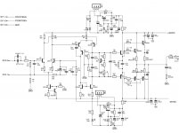
Take a schematic that match your amplifier exactly,measure ALL the transistors Vbe ,mark these on the schematic.Post the schematic here.
What means "anymore"? Was it working before and what have you used instead of the BC550C?If I put a matched pair of BC550C in it the Amp doesn't work anymore
What means "anymore"? Was it working before and what have you used instead of the BC550C?
Update:
If I put just one input differential transistors in the sockets (Q1) nothing gets hot in the circuit, but if i put just Q2 (with and without Q1) in the socket, Q5 gets hot after seconds, but i cant find a short or an other Resistor Value. All Values are alright. If I measure Vbe on Q1 its around 9,6V Vbe on Q2 is 9,6 Volts as well. Q3 has 0,7V. Q4 has 0,7V. On Q5 who gets hot I measure around 22 Volts on Vbe, Q6 has 1,5V Vbe. Q7 has 0,7V. Q8 has 0,7V. Q9 has 0,7 as well.
Any other Infos needed ?
Something is not right. VBE should be no more than 0.7V.
Yeah I know that already but I really don't know what my fault is... that makes me insane !
PS: I measured Q1 and Q2 wrong... Q1 has 0,7V Q2 has 1,5V and its increasing in time... and Q5 has 0,5V and its decreasing as it gets hot ... So something must be wrong there i think ? on the other Pcb i have the same fault.
Last edited:
Can you post a schematic with voltages? Also, what layout are you using? Are you sure your pinout is correct on all of your transistors? My guess is that they are not.
Can you post a schematic with voltages? Also, what layout are you using? Are you sure your pinout is correct on all of your transistors? My guess is that they are not.
I use the Black Beauty PCB from RudiRatlos but i cant upload the PCB plan because the file is too big.
Could it be that the two transistors are just damaged ? Should i replace them ?
Attachments
Last edited:
Without seeing the layout you will have to check and make sure that the base of Q1 goes to R3, the emitter of Q1 goes to R29 and the Collector of Q1 goes to R8. Check the same things for Q2; Base to R7, Emitter to R30 and Collector to R9. BC550 pinout is CBE, left to right with the label facing you. The original amp used MPSA18 which is EBC. Have you tried reversing the two transistors and see if that helps?
Without seeing the layout you will have to check and make sure that the base of Q1 goes to R3, the emitter of Q1 goes to R29 and the Collector of Q1 goes to R8. Check the same things for Q2; Base to R7, Emitter to R30 and Collector to R9. BC550 pinout is CBE, left to right with the label facing you. The original amp used MPSA18 which is EBC. Have you tried reversing the two transistors and see if that helps?
Hi I checked the Pinout, for the Inputtransistors I use 2N5551's but when i changed them to BC550C its the same, the transistor gets hot. The PCB is a printed one. I bought them from diy audioshop. So i think the Pinouts must be correct. It's not the first one I built....
2N5551 is the reverse of BC550.
The voltages at the bases of Q5 and Q6 should be the same.
Yes thank you, i know that. I just ask me what a mistake I made because I made the same failure twice. But I cant find it ...
You say Q1 and Q2 are in sockets. Reverse both of them and try again.
If I put B550C in it reversed as the 2N5551, now Q7 gets hot too after 5 sec ca. ...
Hi Guys,
Just to clear things up. Matching Vbe is pointless. You need to match beta with the two candidate transistors held at the same temperature. You cannot measure beta individually unless you hold the temperature exactly the same for each tested part.
If you have a set of transistors from the same lot, the matched beta pairs will also match Vbe. But matched Vbe parts will vary significantly in beta. The only thing a mis-matched Vbe will bring is a couple mV DC offset. Mis-matched beta will increase distortion and even cause the DC offset to drift with temperature. If the circuit has a zero DC offset by design, beta matched pairs will be the closest to zero mV output offset.
I designed and built a jig for this purpose that works very well. Others have also made it and there are a couple board designs that I see floating around. I have tested three different designs that all work very well. Basically, all it is is a diff pair using a current sink / source for bias and matched resistors for base and collector "loads". Stick the transistors in touching each other, place foam over the pair and a box over the entire mess. In a few minutes you can look at your meter as it is used as a null detector. If the reading is stable, you can see how close the transistors are.
Why people are looking at Vbe is beyond me. It doesn't even make any sense. Match beta folks!
-Chris
- Home
- Amplifiers
- Solid State
- Explendid amplifier designed by Michael Bittner, our MikeB