Hi Chris,
I start to this project for build high power supply (+-65 volt) symasym amplifier.I didnt need more power,only for high speet,more dynamic,very low output empedance..
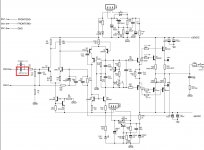
I attacthed my original pcb picture..You can see 36v zener diod and 2 2n5551 transistor.2sk170 working in 36v range.
Working very well means; yes, it sounds good.I connected singnal generator input and connect to osciloscope output (wiht 8 ohm resistif load).
10hz to 100khz gain is ultra linear..good squarewave response.
I haven't spectrum analyzer,i cant measure more detailed..
İf you want,i can give you all document.

I start to this project for build high power supply (+-65 volt) symasym amplifier.I didnt need more power,only for high speet,more dynamic,very low output empedance..
I attacthed my original pcb picture..You can see 36v zener diod and 2 2n5551 transistor.2sk170 working in 36v range.
Working very well means; yes, it sounds good.I connected singnal generator input and connect to osciloscope output (wiht 8 ohm resistif load).
10hz to 100khz gain is ultra linear..good squarewave response.
I haven't spectrum analyzer,i cant measure more detailed..
İf you want,i can give you all document.
Last edited:
Hi caglarm,
You should post whatever you are comfortable with. I think there would be a lot of interest from various members. I have never seen that take on this basic amplifier, so I find it interesting too. If someone else builds one, maybe they can take measurements. One thing for sure, the Symasym basic amplifier sounded very good. I built some. So I'm not terribly surprised to hear you say that yours sounds good too.
-Chris
multisim and eagle files
http://www.diyaudio.com/forums/attachment.php?attachmentid=587092&stc=1&d=1482352241..
http://www.diyaudio.com/forums/attachment.php?attachmentid=587092&stc=1&d=1482352241..
Attachments
Tested and working very well.
HI caglarm
Thank you for your schematic, I suspected that someone has already made an amp with jfet and latfet.
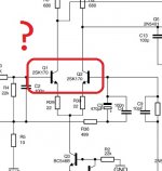
I do not see any driver, where are Q3 and Q4 on your layout/board ?
thanks
Drivers would be a benefit as they drive the gate charge better. This becomes more important at high frequencies.
-Chris
-Chris
When i make first prototype pcb (only 1 per mos,1st pdf file),i use driver transistor.I try some combination.Then i remove driver transistor..sound is more natural.squarewave response is better.I make second pcb without driver and 5 per mosfets.I use this amplifier long time.
BUT,i can say best result transistor out ver.Only one per and high power transistor.(mjl4281-4302)

BUT,i can say best result transistor out ver.Only one per and high power transistor.(mjl4281-4302)
Last edited:
Can I use a 47nF/250V WIMA MKP4 instead of the 10nF ?
Yes, You can use 47nF, if size is OK to solder into the pcb.
Sajti
Yes, You can use 47nF, if size is OK to solder into the pcb.
Sajti
Thanky Sajti !
I have a question about the DC Block capacitor C1, the only purpose of this Cap. is to block DC right ? Can I use a 47nF/250V WIMA MKP4 instead of the 10nF ?
What?
Attachments
the real input filter and DC blocker is the 4u7F capacitor.
The extra small one is sometimes referred to as a bypass.
The extra small one is sometimes referred to as a bypass.
It appears he has picked the BJTs outline that have the same pin out so that the jFETs fit the PCB. And then labelled them so that you see what to use.What?
He has used very low value source degeneration resistors indicating that he realises that these jFETs don't work optimally with the much higher values used by BJTs.
And these 22r are big enough to allow the Builder to check that the jFETs are truly balanced currents.
expect ~30.0mVdc across the degen resistors
and ~1000mVdc across the drain loads. and ~400 to 450mVdc across the CM degen.
Last edited:
I have a problem with my built. I have on one monoamp across the fuses 3,7V instead of 1,5V how it's described in the manual and on the other only 0,5V. All the LED's are working except the Status LED in the SPK Protection Section. I measured all Resistors they are correct. I insulated all screws. Has anyone a solution of this ? Ask if you need more information
Kind Regards
Kind Regards
Have you turned the output bias ON?
Turn the output bias right down till it goes OFF.
Then check voltages around the amplifier to prove that it is assembled correctly.
Turn the output bias right down till it goes OFF.
Then check voltages around the amplifier to prove that it is assembled correctly.
Have you turned the output bias ON?
Turn the output bias right down till it goes OFF.
Then check voltages around the amplifier to prove that it is assembled correctly.
Well, I found the fault but I don't know what I can do now. I have a transistor Socket for Q1 and Q2 (Input differentials) to change Transistors fast to hear the differences in Sound. If I put a matched pair of BC550C in it the Amp doesn't work anymore (I can hear the click from the relais in the SPK protection without inserted BC550C's). Do I need other Transistors like 2N5551 ? In the User Manual there is described you can use BC550C... I'am confused now ...
BTW: without the input transistors the Voltage on the Fuse Sockets is around 0,3V and ALL LED's work ...
The Transistor Q5 gets hot after seconds as well ...
Q5 and Q6 should run at the same temperature, and not hot.
Have you decided to use BJTs instead of J-FETs? Otherwise the BC550C should work fine in that circuit. What are your supply voltages? If you can't find real 2SK170 transistors, try J202 transistors. Much lower transconductance than the 2SK170, but real parts will trump fake parts every time. For BJTs I was using 2SC1775A or 2SC2240s, but the BC550C are low noise, high gain parts that should work great.
Matching J-FETs is straight forward using information from Nelson Pass or Walter Jung. The BJTs need to be matched using a jig (J-FETs use a jig too where you match Vp and Idss) for beta. Vbe isn't important, but will match closely as a side effect of close beta matching from the same batch of transistors. Buying them on tape from the factory (cut tape option from a proper distributor) will insure that.
-Chris
Hi thanks for the reply. Q6 is cold thats why it Brothers me. I mathed all the Transistors except the big powertransistors. I use MJL 1302A and 3281A. Any other ideas what my fault could be ?
Importance of Hfe?
Hi,
seeing these suggestions on transistors I would like to throw in a question: How important is Hfe?
I have obtained Philips NOS 2n5401 and 2n5551. Couldn't find 2N5401 from Fairchild or Onsemi. The old Philips are quite a bit lower in Hfe compared to some newer equivalents from Diotec Semi or Taiwan Semi sold here (30-50%).
The Philips are very nice by appearance and despite quite a variance in Hfe I could match (<0.5% @2mA) good pairs but I am still wondering if high Hfe is important?
Would appreciate if someone could help and explain qhat a difference in Hfe could result in.
- Home
- Amplifiers
- Solid State
- Explendid amplifier designed by Michael Bittner, our MikeB