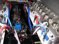
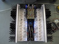
See post 46, there are already 3 holes in the heatsinks, I tapped M5 thread in the big aluminum plate, and each heatsink is mounted to the plate with 3 M5 bolts.
They are visible.
I tested without thermal paste and the heat transfer is already great. But for final mounting I plan to apply a thin layer of thermal paste.
They are visible.
I tested without thermal paste and the heat transfer is already great. But for final mounting I plan to apply a thin layer of thermal paste.
Almost there....
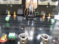
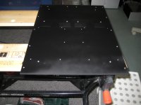
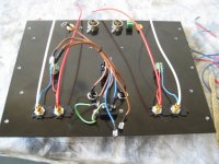
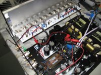
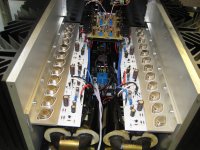
Finished spray painting the 5mm thick bottomplate. The tape is where I want to put the rectifier-bridges and some chassis connections.
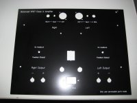
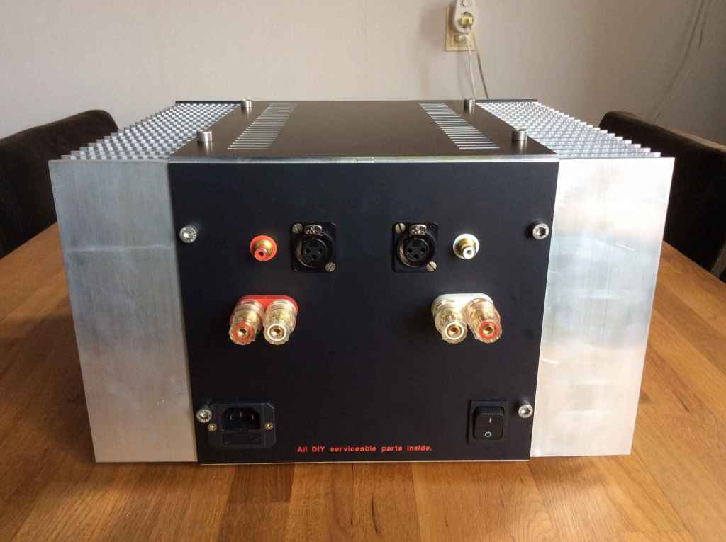
Also the backpanel has arrived from CNC and engraving. It is powdercoated in black. I like it very much. Normally I use anodized black panels, but this seems more scratch resistant.
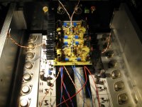
Also the frontend is all wired up and will be the last thing to mount in the chassis.
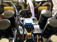
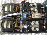
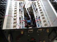
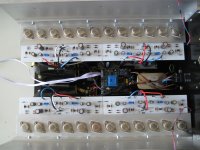
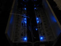
The PSU's are built and tested, everything is working fine. Around 33.5 Volt unloaded. Looks like a big power plant😀
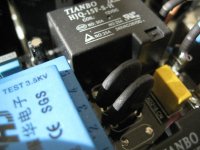
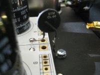
CL-60 from PSU's GND to chassis.
I de-soldered the Chinese NTC's from the softstart boards and replaced them with 2 proper CL-40's in series.
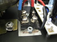
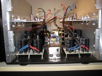
The R-core 500VA transformers have an electrostatic screen, yellow wire, and I put them to chassis also.
The trick is now to have everything wired up before I assemble the whole chassis, cause some connectors like the speaker terminals can not be reached when all is in place.
Attached more pics.
Finished spray painting the 5mm thick bottomplate. The tape is where I want to put the rectifier-bridges and some chassis connections.
Also the backpanel has arrived from CNC and engraving. It is powdercoated in black. I like it very much. Normally I use anodized black panels, but this seems more scratch resistant.
Also the frontend is all wired up and will be the last thing to mount in the chassis.
The PSU's are built and tested, everything is working fine. Around 33.5 Volt unloaded. Looks like a big power plant😀
CL-60 from PSU's GND to chassis.
I de-soldered the Chinese NTC's from the softstart boards and replaced them with 2 proper CL-40's in series.
The R-core 500VA transformers have an electrostatic screen, yellow wire, and I put them to chassis also.
The trick is now to have everything wired up before I assemble the whole chassis, cause some connectors like the speaker terminals can not be reached when all is in place.
Attached more pics.
Attachments
-
 IMG_6198ww.jpg234.1 KB · Views: 790
 -
 IMG_6234ww.jpg486.3 KB · Views: 438
 -
 IMG_6232ww.jpg345.5 KB · Views: 435
 -
 IMG_6228ww.jpg376.8 KB · Views: 407
 -
 IMG_6226ww.jpg431.2 KB · Views: 394
 -
 IMG_6223ww.jpg449.2 KB · Views: 429
 -
 IMG_6221ww.jpg469.2 KB · Views: 751
 -
 IMG_6220ww.jpg449.1 KB · Views: 766
 -
 IMG_6214ww.jpg379.4 KB · Views: 768
 -
 IMG_6206ww.jpg292.7 KB · Views: 781
I like you "only user serviceable parts inside" particularly well!
BTW My experience is to build spacious amplifier chassis to ease accessibility to this and that. Nice build!
BTW My experience is to build spacious amplifier chassis to ease accessibility to this and that. Nice build!
Last edited:
I like you "only user serviceable parts inside" particularly well!
BTW My experience is to build spacious amplifier chassis to ease accessibility to this and that. Nice build!
Hahaha, I must admit I stole the idea from another DIYAudio member😱
Don't remember his name...
Yup you are right, though this is the most spacious amplifier chassis I ever built, I just put in too much stuff 😀😀
Now I must constantly think what to do next, cause I almost have no accessibility to the components beneath the T-brackets with output stage PCB's.
Walter,
are chinese pcb only soft start or they are also with speaker protection function
do you have previous experience In amplifiers with IXYS VBE60 - In other words do you like them
can you tell us their voltage drop when you power everything
are chinese pcb only soft start or they are also with speaker protection function
do you have previous experience In amplifiers with IXYS VBE60 - In other words do you like them
can you tell us their voltage drop when you power everything
Hahaha, I must admit I stole the idea from another DIYAudio member😱
Don't remember his name...
Ahum.....

Hoi ElectroNick, thanks for the idea!
Nice to see you here, you are probably one of the first Dutch subscribers, 2002 join date 😀
Nice to see you here, you are probably one of the first Dutch subscribers, 2002 join date 😀
[offtopic]
...ehh
Seeing what others have built in a few years, i feel like a newbie.
(my Aleph 5 took 8 years to complete 😱 )
[/offtopic]
...ehh
Seeing what others have built in a few years, i feel like a newbie.
(my Aleph 5 took 8 years to complete 😱 )
[/offtopic]
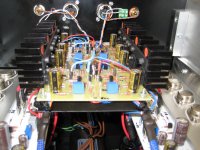
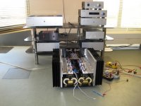
Update, output stages ready, tested and bias adjusted 🙂
Output voltage of my 24 Volts R-core is somehow lower than expected under load. ( 4 Ampere/rail)
They give about 30 Volts, I was expecting around 32 - 34 Volts, cause the smaller R-cores from Selectronics all give way more voltage then specified, but this 500VAs don't.
So I keep the rail voltages at 20.5 Volts to have some regulation for the MOSFETs.
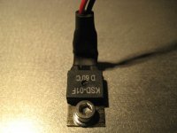
I bought 60 degrees thermal switches, but the wrong type....😡 These switch off at 60 degrees instead of on. Got to have the types with a 'H' on it and not a 'D'.
So I installed the suplied 75 degrees switches.
Amp is now running for two hours and has reached temp equilibrium: 53 degrees at heatsinks, and around 62 degrees on top of the VFET's.
Amp is pulling off 530 Watt from mains. Sick....😉😛🙂
Next is to mount the frontend boards and I'm ready to listen to it.😀
I think a couple of days.
Output voltage of my 24 Volts R-core is somehow lower than expected under load. ( 4 Ampere/rail)
They give about 30 Volts, I was expecting around 32 - 34 Volts, cause the smaller R-cores from Selectronics all give way more voltage then specified, but this 500VAs don't.
So I keep the rail voltages at 20.5 Volts to have some regulation for the MOSFETs.
I bought 60 degrees thermal switches, but the wrong type....😡 These switch off at 60 degrees instead of on. Got to have the types with a 'H' on it and not a 'D'.
So I installed the suplied 75 degrees switches.
Amp is now running for two hours and has reached temp equilibrium: 53 degrees at heatsinks, and around 62 degrees on top of the VFET's.
Amp is pulling off 530 Watt from mains. Sick....😉😛🙂
Next is to mount the frontend boards and I'm ready to listen to it.😀
I think a couple of days.
Attachments
Waaaav Walter, Incredible build, I want to build this amp every time I see a new post from you! Luckily, I have a stock of VFETs that match well enough to do it. Have to wait a bit though since I just finished the VFET amp from the kit and my free time is very limited.
OMG Walter. What an incredible project you have. I look forward to your impressions. 
BTW, any guesses on how much it will weight when completed?
Cheers,
Dennis
BTW, any guesses on how much it will weight when completed?
Cheers,
Dennis
Next is to mount the frontend boards and I'm ready to listen to it.😀
I think a couple of days.
I stay in tune and yes Kudos
 🙂
🙂

Do you Walter have possibility to made celebration video ?
Best regards
Thanks everybody!
Dennis I don't know how much it weights.
I can't lift it from my desktop anymore 😱😱 Need assistance🙂
I have to figure out how to put it on the bathroom scales, because it covers the whole scales and I'm not able to read the display...hahaha
Dennis I don't know how much it weights.
I can't lift it from my desktop anymore 😱😱 Need assistance🙂
I have to figure out how to put it on the bathroom scales, because it covers the whole scales and I'm not able to read the display...hahaha
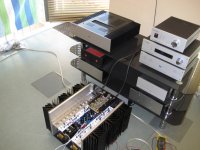
Yeah, making music !!!
It's up and running, all fine. No hum and dead quiet with my ears to the tweeters 🙂😀
Output offset per quadrant is very low <10mV so the resulting output between (+) and (-) is also very low and stable.
I biased a bit higher , starting at around 4.4 Ampere per rail of 30 Volts, so it ends up @54 Celsius at 4.0 Ampere.
It starts with pulling 620 Watts from mains and ends up around 550W fully heated.
When I connected the frontends I had to readjust the output stages, they have influence on each other.
The feedback switch can be switched when the amp is on, you hear no clicks or abnormalities, offset stays the same.
When I switch in the global feedback, the volume goes down for around 6 dB with the 4k75 feedback resistor.
I have been listening to it and it sounds very promising. I can feed the amp only with single ended RCA source for now. But my DDAC1794 has a output transformer so it will not be to difficult to feed it balanced soon and to listen to the full potential of the amp.
For now I can say it's very, very detailed, fast, dynamic, strong bass with authority like my F5Tv3. Soundstage is big and wide, very natural sounding.🙂🙂🙂
I must take some weeks to compare it to my other amps, will let you know.
Next is to design a top plate and a nice frontpanel, Schaeffer AG (Frontpanelexpress) doesn't make thicker panels than 10mm. I would like to have a thick 20mm panel CNC-ed, like the real Passlabs amps and the Sony 40 years VFET amp from Nelson.
Any suggestions are welcome!
What a project this was, took me all winter to build it 😀
Walter
Attachments

It's up and running, all fine. No hum and dead quiet with my ears to the tweeters 🙂😀
Output offset per quadrant is very low <10mV so the resulting output between (+) and (-) is also very low and stable.....
I have been listening to it and it sounds very promising....
What a project this was, took me all winter to build it 😀
Walter
Excellent news WalterW congratulation
After all diy efforts the best part start today
😀
- Home
- Amplifiers
- Pass Labs
- VFET-X (or my 1/3 40th Anniversary Sony VFET Clone)