Thanks, nice video 😀😀
If someone has a video or picture from the backside of this amp, please post. I haven't found it yet.
If someone has a video or picture from the backside of this amp, please post. I haven't found it yet.
Thanks, I will use white goop 🙂
Hello Walter
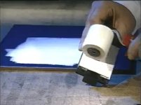
Just visioned this IXYS video and see interesting tip (start at 5:00 min )
how thermal grease goop can be uniformly applicated on the large surfaces with precision.
https://www.youtube.com/watch?v=MqYfXKXfuYQ
Attachments
use your credit card
Platinum or Black for best results (and not expired!) 😀
no, no, no...
creditcards are to be used for the other white stuff...
and this is gettin' off topic!
creditcards are to be used for the other white stuff...
and this is gettin' off topic!

The 'Goop' will be applied when I'm sure I don't have to disassemble it again.
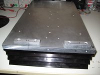
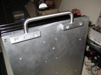
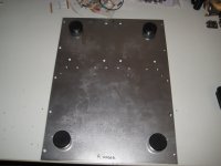
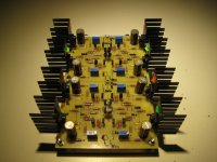
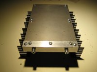
I have been doing most of the mechanical work, drilling, tapping and so on.
Designed and ordered a back plate, and made provision today for 2 handles on the backside.
Made a construction with a 1 mm steel sheet ( hope it's shielding the frontend a bit from the big trannies) for the frontend boards. Which will be mounted high on the backside.
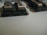
I decided not to make rectifier bridges with 16 separate diodes on heatsinks but I bought 4x IXYS VBE60-6A bridges which will be mounted on the base plate of 5mm aluminum. The IXYS are FRED, fast and soft recovery type and 'low noise' 🙂 A bit expensive although around 20 Euro/piece.
Some pictures of course 😀
Waiting for my soft start boards to arrive from China and my backplate from Germany. Then it's time to build the PSU's and test them.
I have been doing most of the mechanical work, drilling, tapping and so on.
Designed and ordered a back plate, and made provision today for 2 handles on the backside.
Made a construction with a 1 mm steel sheet ( hope it's shielding the frontend a bit from the big trannies) for the frontend boards. Which will be mounted high on the backside.
I decided not to make rectifier bridges with 16 separate diodes on heatsinks but I bought 4x IXYS VBE60-6A bridges which will be mounted on the base plate of 5mm aluminum. The IXYS are FRED, fast and soft recovery type and 'low noise' 🙂 A bit expensive although around 20 Euro/piece.
Some pictures of course 😀
Waiting for my soft start boards to arrive from China and my backplate from Germany. Then it's time to build the PSU's and test them.
Attachments
ZM, can I borrow some of your brain cells again? Or others brain cells....😀
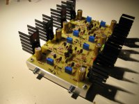
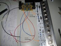
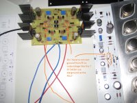
What will be the appropriate way to connect the wires from the frontend outputs to the OS halves? See picture, the long wire is approx. 30 cm, not able too twist with the other wire for the positive half. Because both (+) and (-) inputs from the output stages are about 22 cm from each other.
Or use coaxial cable and put shield to GND at one point at the front side boards only? To avoid ground loops.
If I look at Passlab amps I see Papa is using ribbon cable 😱
Other question is of course.... about..... GND 🙂
There is almost no ground in this balanced amp, but my thinking was to let all grounds in the amp go to a star formed at the PSU boards GND, to avoid ground loops. And from that starpoint a CL60 to chassis.
Or should the GND from the frontend go to the output stages as in the picture?
Attachments
Last edited:
wires try twisted pairs (+ & GND , - & GND)
in case of problem (not likely) , use - as you say - coax with pair inside , screen grounded on upstream (FE pcb ) side
CL60 , agree - from PSU pcb to case
signal gnd wire for OS , take it from FE pcb
in case of problem (not likely) , use - as you say - coax with pair inside , screen grounded on upstream (FE pcb ) side
CL60 , agree - from PSU pcb to case
signal gnd wire for OS , take it from FE pcb

Walter
great craftsmanship
would you please give details about black vertical heatsinks 2 x 3 pcs - can they be purchased online
great craftsmanship
would you please give details about black vertical heatsinks 2 x 3 pcs - can they be purchased online
1pcs Pass high-power class A amplifier heatsink/ radiator 260mm*150mm*75mm | eBay
Scroll down, at the description black anodized is mentioned.
Scroll down, at the description black anodized is mentioned.
- Home
- Amplifiers
- Pass Labs
- VFET-X (or my 1/3 40th Anniversary Sony VFET Clone)