Question:
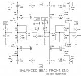
If you look at the attached schematic from BBA3 frontend. If I short "-IN" to ground for non balanced behavior, you'll expect to have shut down the negative half of the amplifier and have no output signal on the "-OUT".
But when measuring with AC-voltmeter I discovered there is still music output on "-OUT" ???
Is it because of R5? The two 100 Ohm resistors who normally go to ground but are now connected together forming a 200 Ohm resistor? Is it modulating the negative side from the positive side?
Can someone explain how this works? 😕
Attachments
You have a differential amp.
If you understand how a folded cascode amp works then you should also be able to visualize how this front end works.
Think about it more, you are on the right track.
If you understand how a folded cascode amp works then you should also be able to visualize how this front end works.
Think about it more, you are on the right track.
Thanks pico, but I was hoping for a more detailed explanation. Google doesn't give much relevant answers, all about opamps...
Somebody?
Somebody?
imagine how's working LTP (especially when you introduce source (emiter in case of bjts) resistors
then just imagine these two FEs as LTP halves
it's simple
then just imagine these two FEs as LTP halves
it's simple
yup
though , this time think just of feedback effect (AC domain) , not DC domain
if you observe source resistors in LTP as degeneration parts/devices , then observe common source rail as feedback/degeneration route;
though , this time think just of feedback effect (AC domain) , not DC domain
if you observe source resistors in LTP as degeneration parts/devices , then observe common source rail as feedback/degeneration route;
Hi Walter,
Is your amp now compete? I remember a while back you were working on the
front plate?
Cheers,
Dennis
Is your amp now compete? I remember a while back you were working on the
front plate?
Cheers,
Dennis
Hi Walter,
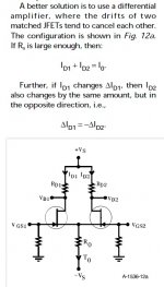
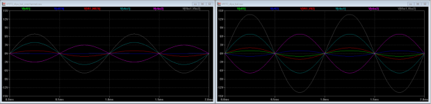
Here is an additional ltspice simulation I did using the DIYA VFET balanced frontend with IRF9240/IRF240 common drain outputs (like in the M2).
It does not have the VFETs in the simulation, but it shows pretty well (I think) what's going on.
Indeed the channel you tried to shut off with grounding the IN- is still half fed by the R332/R322 resistors as a feedback signal to the jfets. If you additionally ground the middle of the R332/R332 resistors your minus channel is at 0 volt output.
In the 2 attachments you see the "half" amp left and the full differential amp on the right. One picture is the front end Jfet and mosfet outputs, the other has the in/output signals.
in/output pic: green=IN+, blue=IN-, red=IN+-, cyan=OUT+, purple=OUT-, gray=OUT+-
jfet/fe: green=jfet+, blue=jfet-, red=middle off R332/332, cyan=fe_out+, purple=fe_out-
Had this simulation on hand for trying to understand my diya balanced vfet2 build.
Attachments
Hi Walter,
Is your amp now compete? I remember a while back you were working on the
front plate?
Cheers,
Dennis
Haven't really got the time for working on the front panel. I did had an offer from a member to put my design of the front panel in AutoCAD, so I can order at a professional firm.
Schaeffer doesn't do front panels thicker than 10 mm, same with Modushop.
I made the design for the top plate which is going to look nice 🙂
But I have to experiment with blue LED's and Perspex before ordering...
Does anybody know an easy to learn program, I can use to design a front panel?
Like Frontpanel express (Schaeffer) ?
Like Frontpanel express (Schaeffer) ?
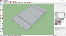
it depends - if for fabrication sort of workshop drawing is enough ( no need for specialized CAD file ) , then SketchUp is enough
I did several files for fabrication that way , and printed sheet is all what proper machinist needs
I did several files for fabrication that way , and printed sheet is all what proper machinist needs
I have used FPE then used it's export to dxf option and the shop I have used have been fine with that. Best of luck
Sent from my SM-G930F using Tapatalk
Sent from my SM-G930F using Tapatalk
There's this online tool https://www.onshape.com
It's for free if the designs are open to public. It's very capable and simple to use.
Martin
Sent from my HTC 10 using Tapatalk
It's for free if the designs are open to public. It's very capable and simple to use.
Martin
Sent from my HTC 10 using Tapatalk
I use FPE for all kinds of things. Super useful!! The export option is a good idea. Also very happy with the FPE service the one time I used it. My engineer son has fancy Autodesk CAD software, but wow the learning curve...
BK
BK
Only designing, so I can let it produce in a CnC shop.
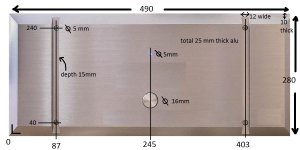
Attached is what I want to be designed, 25 mm thick brushed aluminum with the front edges like in the picture, but I don't know how to describe it in the picture.
In FPE it is called front edge bevel 30 degrees or 45 degrees with a depth of certain amount of mm's.
Attached is what I want to be designed, 25 mm thick brushed aluminum with the front edges like in the picture, but I don't know how to describe it in the picture.
In FPE it is called front edge bevel 30 degrees or 45 degrees with a depth of certain amount of mm's.
Attachments
This part will cost you an arm!
ok, give me 2 days and I send you the datas (STEP and all others, designed with SolidWorks).
Jean-Paul
ok, give me 2 days and I send you the datas (STEP and all others, designed with SolidWorks).
Jean-Paul
What a great forum this is, this gathering of DIY fanatics 😀
Member Jotom750 sent me this beautiful piece of artwork.
Thanks Richard!
Another member showed me a CnC company and some examples how to order with them. Thanks also!
With this PDF I can start ordering my frontpanel, get some quotes.
🙂🙂🙂
Member Jotom750 sent me this beautiful piece of artwork.
Thanks Richard!
Another member showed me a CnC company and some examples how to order with them. Thanks also!
With this PDF I can start ordering my frontpanel, get some quotes.
🙂🙂🙂
Attachments
- Home
- Amplifiers
- Pass Labs
- VFET-X (or my 1/3 40th Anniversary Sony VFET Clone)