For me it would still be interesting see another tweeter measured in exactly same chain because they don't track close and from about 4,5kHz absolut phase start lagging direction but minimum phase doesn't.
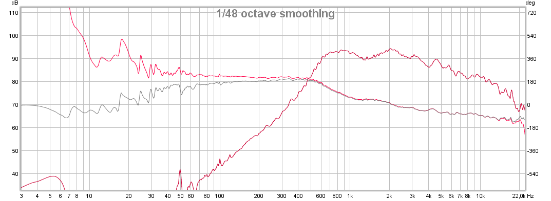
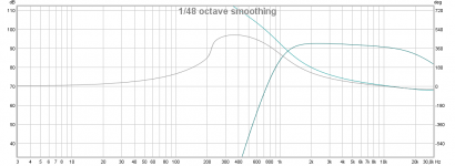
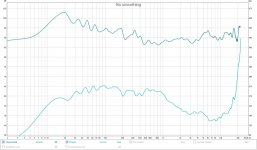
Here is my raw 2426H 1/48 smoothing:
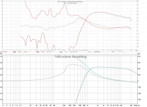
Here is my raw 2426H 1/6 widht in octaves FDW:
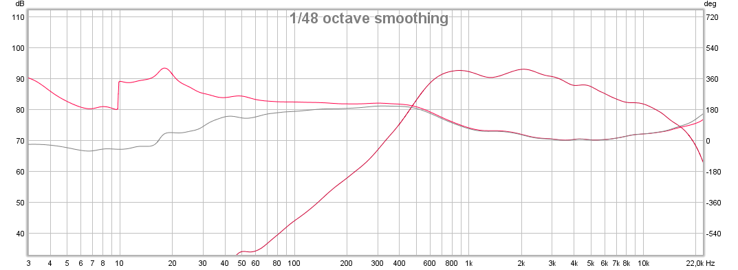
See how they track above even phase change between the two 🙂
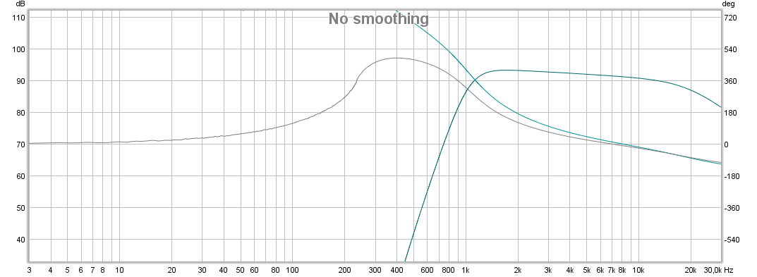
Here is reference IR for your tweeter bandpass no FDW:
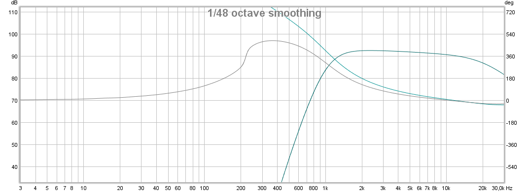
Here is reference IR for your tweeter bandpass with FDW 1/6 widht in octaves and interesting how knee of slope gets softer:
Here is the reference FDW 1/6 widht in octaves verse live BMS:
By the way some versions of REW can introduce some errors here and there, any chance we fight a unfortunate version here.
Here is my raw 2426H 1/48 smoothing:
Here is my raw 2426H 1/6 widht in octaves FDW:
See how they track above even phase change between the two 🙂
Here is reference IR for your tweeter bandpass no FDW:
Here is reference IR for your tweeter bandpass with FDW 1/6 widht in octaves and interesting how knee of slope gets softer:
Here is the reference FDW 1/6 widht in octaves verse live BMS:
By the way some versions of REW can introduce some errors here and there, any chance we fight a unfortunate version here.
Attachments
Last edited:
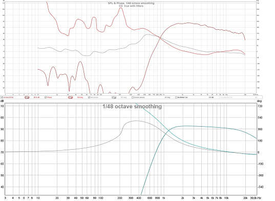
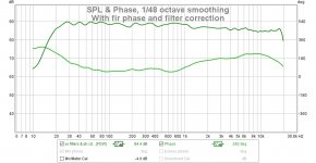
I know, that LF noise is suspicious. Let me remeasure. These are hot off the mic. Filters are from yesterdays CD INV XO that uses both XO filter linearization and phase correction from just under 1 Khz up.
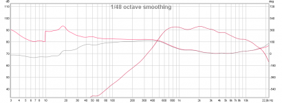
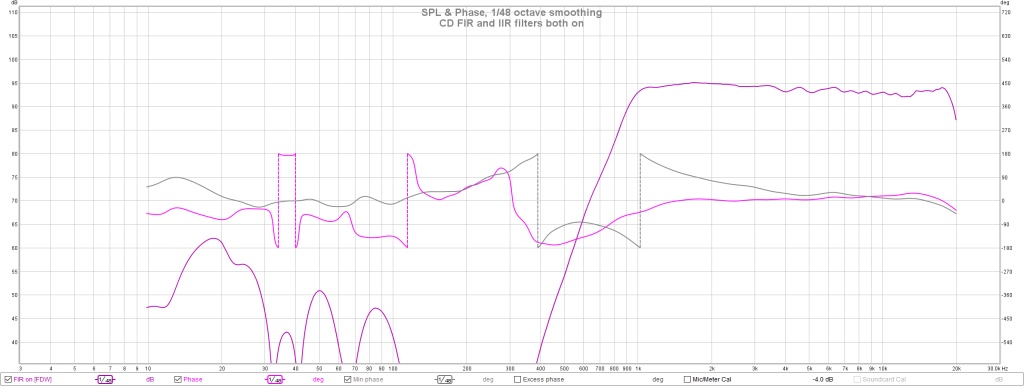
This is with FIR on
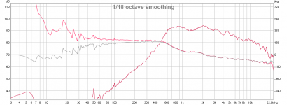
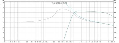
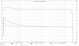
This is with only IIR filters
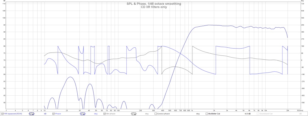
There is still some LF noise but its a lot further down
This is with FIR on
This is with only IIR filters
There is still some LF noise but its a lot further down
Attachments
Hi BYRTT:
I see how nicely behaved the phase is in your system. Mine is not so nicely behaved but I don't see anything worrisome in the phase corrected version - the first of the two I just posted - other than the fact that its smoother than the min phase
I see how nicely behaved the phase is in your system. Mine is not so nicely behaved but I don't see anything worrisome in the phase corrected version - the first of the two I just posted - other than the fact that its smoother than the min phase
Hi BYRTT:
I see how nicely behaved the phase is in your system. Mine is not so nicely behaved but I don't see anything worrisome in the phase corrected version - the first of the two I just posted - other than the fact that its smoother than the min phase
That is alright opinion 🙂 but highest XO point will never sum as beatifull as lower XO point if not investigated why tweeter bandpass isn't behave as minimum phase device, and no matter what is the truth to that bandpass it can be corrected to be perfect and sum by the book but it will probably need its own selected box as suggested some posts ago add APL1 to that passband.
I know, that LF noise is suspicious. Let me remeasure. These are hot off the mic. Filters are from yesterdays CD INV XO that uses both XO filter linearization and phase correction from just under 1 Khz up.
This is with FIR on
This is with only IIR filters
There is still some LF noise but its a lot further down
See how you try to undo the inverted polarity of the CD connection in FIR correction?
If you take the second graph, it would be almost right if you flip it back to normal polarity.
Just flip the phase back of the CD, redo the RePhase phase correction and the STEP will be as you want it to be. Just look at my post with the FIR corrected version of your earlier setup. That one does not have a dent at the crossover frequency.
Last edited:
I didn't get around to trying that today or even thinking about it. If I just flip the CD polarity, I'll have a big dip just past the xo point. Will fixing the phase fix that? I guess it should given that its eqed to fit the target curve fairly closely.
Not to ruin the suspense, but it looks like the magicians and tea readers may be going to rule the day.
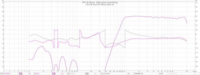
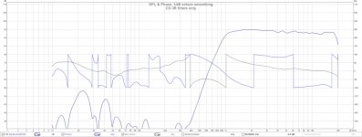
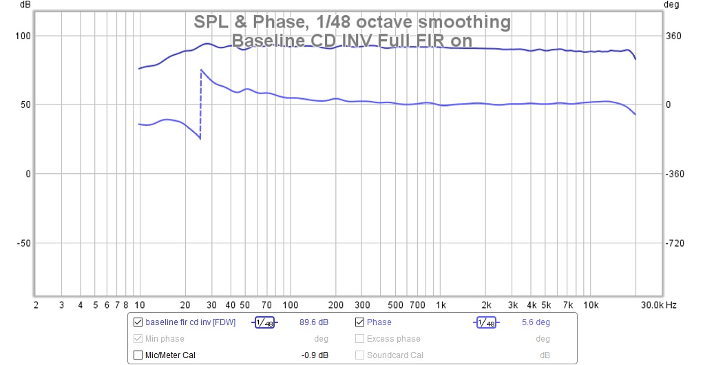
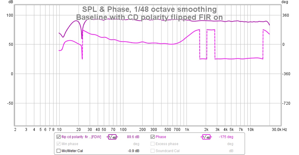
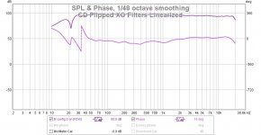
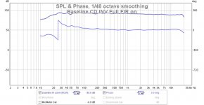
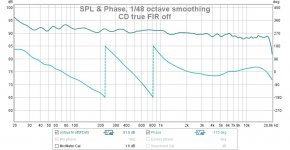
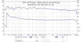
Here is the baseline measurement for CD INV, filters linearized and phase corrected
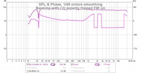
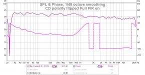
Here is what it looks like with CD polarity flipped back to true. Surprisingly to me at least no DIP in the FR at xo results
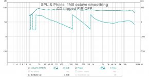
Let's now turn FIR all the way off and see two phase turns where reference shows 3
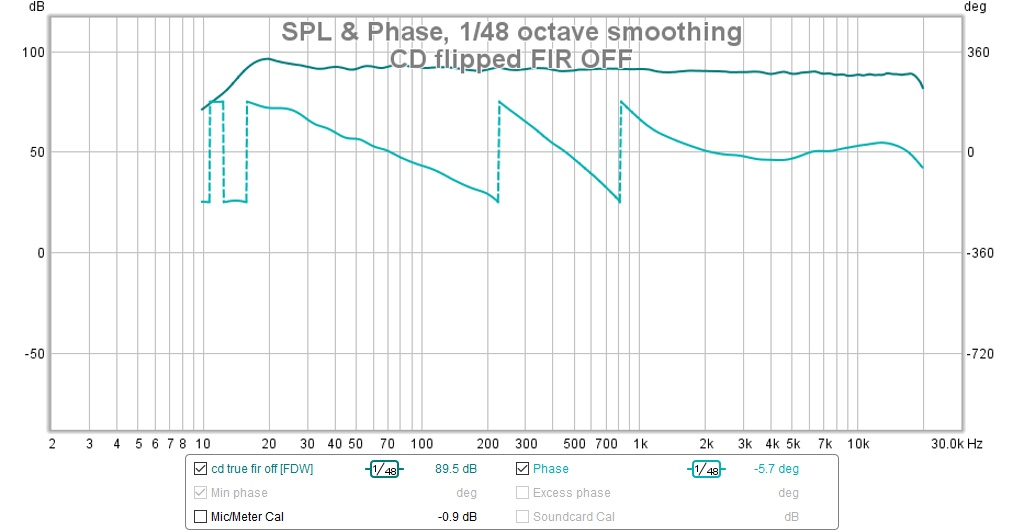
Now lets turn just the XO filter linearization FIR on
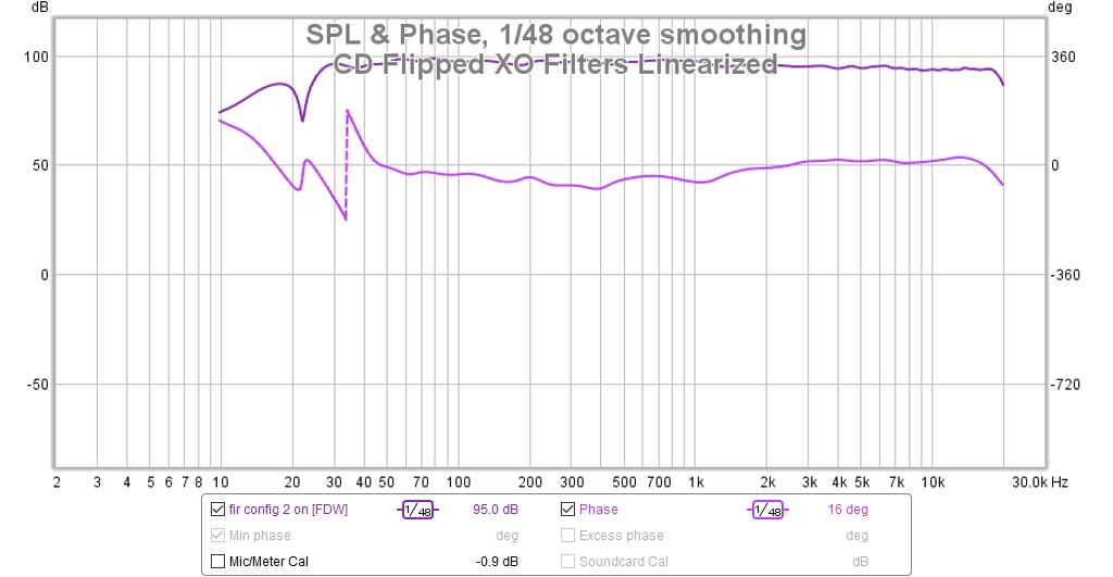
Next I'm going to export that last measurement to REW and make a phase correction for roughly 1 khz up. I'm not sure what that will do for the step but right now it needs some help, as you can see below.
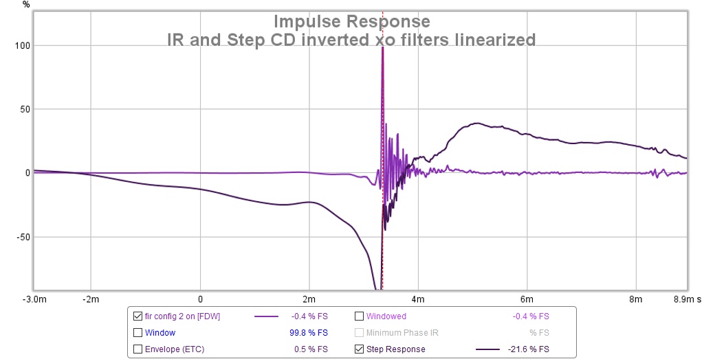
I should also check IR peak alignment...
I have no idea why that 20 Hz null appears with CD polarity flipped to true.
Let me repost these figs at better scale
Here is the baseline measurement for CD INV, filters linearized and phase corrected
Here is what it looks like with CD polarity flipped back to true. Surprisingly to me at least no DIP in the FR at xo results
Let's now turn FIR all the way off and see two phase turns where reference shows 3
Now lets turn just the XO filter linearization FIR on
Next I'm going to export that last measurement to REW and make a phase correction for roughly 1 khz up. I'm not sure what that will do for the step but right now it needs some help, as you can see below.
I should also check IR peak alignment...
I have no idea why that 20 Hz null appears with CD polarity flipped to true.
Let me repost these figs at better scale
Attachments


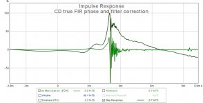
I got interrupted but I did complete a trial run of correcting the phase for the CD true case. Results indicate need for more detective work.
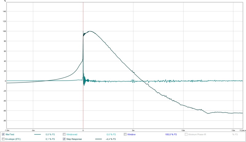
Here is the FR and phase. Phase did not come out flat and there is a 1.5 db dip just past the 1050 hz XO, likely easily corrected by PEQ.

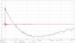
Here is the IR and step

It looks to my uneducated eyes that the CD is firing late and in the wrong direction. Perhaps the phase changes upset the driver alignment but there is still the polarity issue. I have to dig deeper but I can't do that right away.
Here is the FR and phase. Phase did not come out flat and there is a 1.5 db dip just past the 1050 hz XO, likely easily corrected by PEQ.
Here is the IR and step
It looks to my uneducated eyes that the CD is firing late and in the wrong direction. Perhaps the phase changes upset the driver alignment but there is still the polarity issue. I have to dig deeper but I can't do that right away.
Attachments
It looks to my uneducated eyes that the CD is firing late and in the wrong direction. Perhaps the phase changes upset the driver alignment but there is still the polarity issue. I have to dig deeper but I can't do that right away.
Only the top end fires late, which will dominate how an IR is shown. If we correct this top end phase, the IR should look better.
Here's the convolved correction for that older wave file you uploaded:
As can be seen it corrected the phase of the top end compared to the mid/low end. (and a lot more)
Attachments
Last edited:
Just ran my correction again on that older wave file you posted, this time with a flat target.
In no particular order I'll show the pictures:

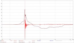
Frequency, phase and generated phase

IR and STEP

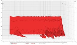
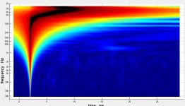
Early waterfall plot

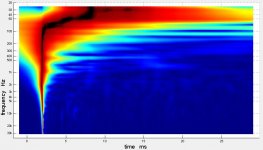
Wavelet showing no dents...
In no particular order I'll show the pictures:
Frequency, phase and generated phase
IR and STEP
Early waterfall plot
Wavelet showing no dents...
Attachments


Other than the low frequencies that don't get fixed by my specific settings the crossovers at 1050 and 300? get the royal treatment and show no dents anymore:

Based on this IR/STEP:

I had to convert back and forth between 44100 and 48000 because I simply don't have my templates set up for 48000.
This still is with specific settings for my arrays. Gentle clean up based on very short frequency windowing. That's why the bass doesn't get cleaned up entirely I suppose. I have very conservative settings, feathering the phase response into shape.
This is what I started with, your wave file as viewed in TDA:

And the IR/STEP:

Based on this IR/STEP:
I had to convert back and forth between 44100 and 48000 because I simply don't have my templates set up for 48000.
This still is with specific settings for my arrays. Gentle clean up based on very short frequency windowing. That's why the bass doesn't get cleaned up entirely I suppose. I have very conservative settings, feathering the phase response into shape.
This is what I started with, your wave file as viewed in TDA:
And the IR/STEP:
Attachments
Last edited:
nc535,
You probably had other settings for delays at that time maybe a good idea start use them and stay there or investigate if small steps from there can improve bit further. The reference models can tell timings where IR and SR sits down the time line be it pure IIR domain or the XO linearized domain and copying these should get you going, but in that tweeter is not normal IIR domain by the book there has to be some deviation from reference.
Regearding linearize the 80-120º phase lag for tweeter wonder if you seen in Rephase on "Minimum-Phase Filters" tab you can pick "1st order All-Pass" and think if set at 1050Hz or 4500Hz will help some for tweeter section. Would still like to see another tweeter hanged on to same chain to confirm if the lag fault is really there or we just look at visual presented errors.
wesayso,
Your self educated EQ skills is simply first class 🙂 can you create a automatic plugin for JRiver then i buy a license or two.
wesayso,
Your self educated EQ skills is simply first class 🙂 can you create a automatic plugin for JRiver then i buy a license or two.
DRC-FIR is free, you know? 😀
It's the secret sauce that makes it work and sound clean though.
Did you notice my IR with flat FR target has zero pre-ringing? 🙂
DRC-FIR is free, you know? 😀
It's the secret sauce that makes it work and sound clean though.
Did you notice my IR with flat FR target has zero pre-ringing? 🙂
Noticed the improbable zero preringing 😀 its a very good sauce 🙂
the true price is the hours you spend learning how to use it.
The results you obtain with it are impressive, maybe its worth it. I'm thinking I'm going to have to break down a buy another PC for a music server sooner or later.
I tried re-aligning IR peaks. They were quite far out of alignment - far enough to make the phase correction or the process by which it was developed suspect and after all, it didn't work. The CD had to be moved .12 ms closer to the mid and both of them had to move about .5 ms to align on the woofer peak. That still wasn't quite right but I didn't want to reduce the CD delay below zero 🙂
The process was to align IR peaks with xo filter correction FIR on, measure FR and phase, then add a paragraphic phase EQ in Rephase based on the REW measurement. This assumes the paragraphic EQ won't shift driver time alignment. Apparently, it does. Perhaps I should leave phase untouched below some frequency?
Reading tea leaves is a good first step 🙂. There's more to the IR than meets the eye. That's the most important thing to learn. All this software is fun to play with but in the end it's just plain math.
You, as the user has to be in control of what you want. Most of my time was spend on that. Listening to all kinds of processing variants to learn. Long windows, short windows, windows independent from frequency etc.
You can't force anything into shape and expect good (sounding) results. That's why I try to minimise the processing as much as I can. Can you solve something another 9more physical) way? Go with that!
The result you had one page ago, with the CD back to previous polarity was close. Did you try my REW trick, filtering the frequencies close to the crossover with 1/3 octave filters? Don't align IR's, align the wave front.
Don't align IR's, align the wave front.
Care to expand on this one? 😕
//
I did a page or so ago.... You can zoom in on the frequencies within the IR rather than depend on the IR itself.
http://www.diyaudio.com/forums/multi-way/291160-my-synergy-corner-horn-bass-bins-48.html#post5008774
Try it with a virtual setup. Combine the output of the two virtual drivers with REW's (A + B) sum function in the SPL tab.
The IR is a 'rendering' of all the frequencies to show what's going on. All other graphs are based on it. So all the information is there, for us to use. Yet a standard IR for a full range sound mainly shows us the top end response. Those peaks are nice and sharp, easy to align. The further down we go, the more difficult it gets to really see what's going on. Especially with "real life" woofers. Crossovers change the rendering of the IR.
In a perfect setup we can calculate the needed delays. In our real world we need to measure as we don't know the exact position of the acoustic centres. So to still be able to compare apples with apples, why not filter the IR and look where the summing happens.
I'll admit, 1/3 octave filters won't show us all, but we can align the wave shapes.
Set the filters on the Filtered IR tab, go back to the IR tab to see the wave shapes. Use the overlay button to see more than one IR.
- Home
- Loudspeakers
- Multi-Way
- My Synergy Corner Horn and Bass Bins