That's what is pulling your DC voltage down.
44mA current instead of 12mA current.
I don't understand - I think I used the ESP recommended relay (16A version). 44mA is normal for this relay I think. I'm confused. Thanks anyway.
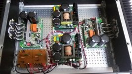
Since I wanted to include a power LED I decided to mount the power supply horizontal.
The power LED is a warm white and I’m using a 10k resistor to limit the current and therefore the brightness as well. I don’t want the LED to be too bright…
popchops what your thoughts about mounting an 'On' indicator on 'our' case?
problem is the thickness of the front panel
Last edited:
Hi Calpe... I have thought about it. It's a nice touch. I will be able to see the PCB led through the top vents but if I was confident in machining a neat LED mounting it would be better to have something on front. Not a priority for me right now though.
Very true Popchops. I was very anxious even having threaded the holes on the heatsinks!
If i find anything i'll post it here
Best of luck
If i find anything i'll post it here
Best of luck
popchops what your thoughts about mounting an 'On' indicator on 'our' case?
problem is the thickness of the front panel
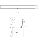
You could do it like this (see attached picture):
* drill a 1,5 mm hole all the way through the front panel
* from the back of the panel, drill a 3 mm hole (for a 3 mm LED) about 4 or 5 mm deep
* insert the LED from the back
* use hot glue, at the back, to hold the LED in place.
The result is a tiny hole in the front from where the light will emit. Use a quite high resistor in front of the LED to limit the current (and light). You don't want the LED to bright. Personally I like a white LED
Attachments
I don't understand - I think I used the ESP recommended relay (16A version). 44mA is normal for this relay I think. I'm confused. Thanks anyway.
Popchops, I agree with Andrew:
Instead of using an unregulated power supply as in the ESP P39 project, use a regulated ps. You'll need a transformer with a higher AC output voltage. An then use a simple LM7812 regulator. (use a heatsink for the LM7812 !!!). The LM7812 will need at least 3 volts drop over the device, so you'll need an AC output of at least 12 volts.
This way you'll have a softstart you can trust even when the mains voltage drops. Note that there is a tolerance allowed on the AC mains supply in Europe (and I guess elsewhere). In your current situation you'll probably have an issue if the mains voltage drifts towards the down side of the tolerance (your relays won't initiate).
Also, I would advice to mount a diode accross relay RL1. Elliot is relying on D1 and D3 of the rectifier but I would not trust that. A simple 1N4148 diode is very cheap; to cheap to leave out that diode across that relay.
Last edited:
I will be able to see the PCB led through the top vents but if I was confident in machining a neat LED mounting it would be better to have something on front.
Note that the red LED used on the PCB is not very bright...
Found the fuse holders
Chassis Mounting 20mm Fuseholder | Maplin
I don't know if you can see it in the pictures I have attached but I applied some hot glue under the solder lips after soldering the wires to the fuses. The hot glue provides support and additional strength to the solder lips of the fuses so they won't break under the stress of the wires (I use 2,5 mm2 wires).
Thanks for the suggestion Delange, a great idea, though i wish my skills were as good as yours!
Will also check out applying hot glue under the solder tabs of the fuse holder, thanks
Will also check out applying hot glue under the solder tabs of the fuse holder, thanks
Guys, what your opinion about using something from here, maybe a panel mount or just stick to Delange original idea?
Blue Cool White Green Single Colour LED Panel Mount Indicators | Farnell element14
Cheers
Blue Cool White Green Single Colour LED Panel Mount Indicators | Farnell element14
Cheers
Guys, what your opinion about using something from here, maybe a panel mount or just stick to Delange original idea?
Blue Cool White Green Single Colour LED Panel Mount Indicators | Farnell element14
Cheers
This is again personal taste.
Me, I don't like those black or shiny LED holders and prefer to hide the LED (as described above).
But of course, that is only my optinion and taste. Others might feel different.
What about using an ordinary "unmounted" LED @ ~2cents poking through a hole in the front plate. Green for good to go is my code.
Red for a fault indicator.
But the colour is down to the preference of the user.
If the leads are long then twist them to contain any interference that might be on the DC level.
Red for a fault indicator.
But the colour is down to the preference of the user.
If the leads are long then twist them to contain any interference that might be on the DC level.
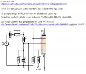
Just a small bit of info based on the 'delange' input level pot.
Might be useful for some.
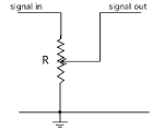
Calpe, be careful because the schematic you posted is not correct:
* from C1 connect to "signal in"
* "signal out" connects to R1
* see attached picture for "signal in" and "signal out" connections
Attachments
Thanks Delange for your detailed reply. If I have problems with soft start I'll definitely go for a small regulated power supply.
In the meantime I have a question on max DC voltage for the Q-Watt. There are two conflicting figures given by Elektor: 60V (in the main article) and 57V (in comments). I need to know how to dimension the transformer at max mains voltage and low load. Will the Q-Watt tolerate say 58.5V? Then my nominal will be around 55V.
In the meantime I have a question on max DC voltage for the Q-Watt. There are two conflicting figures given by Elektor: 60V (in the main article) and 57V (in comments). I need to know how to dimension the transformer at max mains voltage and low load. Will the Q-Watt tolerate say 58.5V? Then my nominal will be around 55V.
Thanks Delange for your detailed reply. If I have problems with soft start I'll definitely go for a small regulated power supply.
In the meantime I have a question on max DC voltage for the Q-Watt. There are two conflicting figures given by Elektor: 60V (in the main article) and 57V (in comments). I need to know how to dimension the transformer at max mains voltage and low load.
From the Q-Watt article:
Code:
±56 V, provided by a transformer with two 40 VAC secondariesThe absolute max voltage is ±60 volts.
My amps are running of SMPS's who provide ±55 volts.
Will the Q-Watt tolerate say 58.5V? Then my nominal will be around 55V.
Yes it will.
Thanks Delange. 40 V secondaries would give me 57V nominal (@ 240V) and worst case > 60V. And that's assuming a 240V primary. If it's the recommended 230V nuvotem then... way in excess of 60V in case of max mains supply (253V)
So Elektor advice doesn't really work in the UK. I think I will specify 2x 38.5V toroids and 240V primary. Fortunately I live across the road from a small substation so my mains always seems to be 240ish.
So Elektor advice doesn't really work in the UK. I think I will specify 2x 38.5V toroids and 240V primary. Fortunately I live across the road from a small substation so my mains always seems to be 240ish.
Attachments
Last edited:
Thanks Delange. 40 V secondaries would give me 57V nominal (@ 240V) and worst case > 60V. And that's assuming a 240V primary. If it's the recommended 230V nuvotem then... way in excess of 60V in case of max mains supply (253V)
So Elektor advice doesn't really work in the UK. I think I will specify 2x 38.5V toroids and 240V primary. Fortunately I live across the road from a small substation so my mains always seems to be 240ish.
Can you explain how you calculated these values?
In my opinion, you should first calculate the "deviding factor" (sorry don't know the correct English term) of the transformer:
230v / 40v = 7,75 (deviding factor). So if the mains voltage rises to 240 volts, this transformer would output 240 / 5,75 = 41,74 volts. After rectifying and buffer caps, the voltage would be 58,4 volts DC. This means you are fine with a 2 x 40 volts output transformer.
EDIT: okay, just saw what you mean... To be on the safe side you could use a 2 x 35 volts transformer. That will certainly work in your use case.
http://www.farnell.com/datasheets/1909346.pdf
Last edited:
Guys, this transformer might also be helpful, can't remember at the moment but i believe it was in the Elektor component list: -
0500P1-2-040 | 2 Output Toroidal Transformer, 500VA, 2 x 40V ac | Nuvotem Talema
Its a 2 Output Toroidal Transformer, 500VA, 2 x 40V ac, priced at £68.54
delange, sorry for the wrong diagram in the earlier post, i'll correct it tomorrow from work
0500P1-2-040 | 2 Output Toroidal Transformer, 500VA, 2 x 40V ac | Nuvotem Talema
Its a 2 Output Toroidal Transformer, 500VA, 2 x 40V ac, priced at £68.54
delange, sorry for the wrong diagram in the earlier post, i'll correct it tomorrow from work
Last edited:
- Home
- Amplifiers
- Chip Amps
- My Q-Watt project