I don't think they will continue to sell them, they wouldn't throw them out if that would be the case.
Elektor did not through them out. They where out of stock (sold out).
I'm using GBPC3504W, one for each power rail. Measured loss (AC-DC) = 2.74V.
Hi Calpe. I know the specs but I can't really explain why my DC is 2.7V less than AC x 1.414.
It must be 2x diode drops of approx 1V, and another 0.7V lost... somewhere... between the bridge rectifier and first capacitor.
Pops.
That's exactly the reason. While it's often within the tolerance to ignore that on higher voltage power supplies, at such low voltages it's often a game-changer.
I don't see any reason to use two bridges, one per rail. One for both will do fine and reduce voltage and (output) power loss significantly.
Best regards!
It's specified in the Elektor article to use one PSU for one Q-Watt amplifier board.
Ive done this using two decent quality SMPS.
The original bridge rectifier listed by Elektor is a: -
GBPC3502 - FAIRCHILD SEMICONDUCTOR - Bridge Rectifier Diode, Single, 200 V, 35 A, Module, 1.1 V, 4 Pins | Farnell element14
It's Vf - Forward Volatge Drop per bridge is 1.1V (max).
NB: 1.1V per bridge not per diode!
Last edited:
It's specified in the Elektor article to use one PSU for one Q-Watt amplifier board.
Ive done this using two decent quality SMPS
Then you don't need any additional rectifier bridge at all?!?
Best regards!
Edit: I saw you weren't the one who uses two bridges. It is popchops, instead. Pardon me!
Last edited:
Taken from the article:-
Power Supply (for one amplifier)
Power transformer: sec. 2x40V, 500VA (e.g. Nuvotem 0500P1-2-040 for 230 VAC mains)
Bridge rectifier: 200V, 35A (e.g. GBPC3502) (Fairchild)
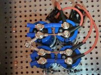
Four 10,000μF, 100V electrolytic capacitors (2 in parallel on each supply rail)
Power Supply (for one amplifier)
Power transformer: sec. 2x40V, 500VA (e.g. Nuvotem 0500P1-2-040 for 230 VAC mains)
Bridge rectifier: 200V, 35A (e.g. GBPC3502) (Fairchild)
Four 10,000μF, 100V electrolytic capacitors (2 in parallel on each supply rail)
Yep thanks ICG. I did some more testing and more reading. Seems like my rectification losses are closer to 3.1V per rail... so thats say 2x 0.9V diode drops plus another 1.2V dropped somewhere.
If I was using a single bridge spanning both rails then I guess each rail only pays 1x 0.9 diode drop. Might be worth remembering if I need to tweak up the voltage later.
But where / how am I losing the other 1.2V at idle?
If I was using a single bridge spanning both rails then I guess each rail only pays 1x 0.9 diode drop. Might be worth remembering if I need to tweak up the voltage later.
But where / how am I losing the other 1.2V at idle?
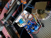
Shown also in post 138:
http://www.diyaudio.com/forums/chip-amps/301100-my-q-watt-project-14.html#post4996549
http://www.diyaudio.com/forums/chip-amps/301100-my-q-watt-project-14.html#post4996549
Attachments
Last edited:
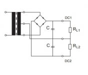
1st: Change to the one bridge design that calpe shows.
2nd: Get rid of these fuses at the secondaries. Remember your big filter capacitor(s). The larger the value, the shorter the charging pulses, the bigger the charging currents per pulse. These fuses, together with their holders, ad substantial ohmic losses!
Best regards!
2nd: Get rid of these fuses at the secondaries. Remember your big filter capacitor(s). The larger the value, the shorter the charging pulses, the bigger the charging currents per pulse. These fuses, together with their holders, ad substantial ohmic losses!
Best regards!
Calpe's circuit would result in lower diode voltage drop, but I think the dual-rectifier circuit will be quieter. I need to choose a transformer that will allow me to try both configurations - thats why I'm checking the losses. Should be only 1 diode drop difference per rail.1st: Change to the one bridge design that calpe shows.
Silencio!!! Hospital para fuentes de alimentación!!!
http://www.diyaudio.com/forums/power-supplies/302628-power-supplies-differences-3.html#post4964660
Is it true too that each bridge handles less power? Reduced workload?
Agreed - I need some advice on fusing the 55V side. Some say:2nd: Get rid of these fuses at the secondaries. Remember your big filter capacitor(s). The larger the value, the shorter the charging pulses, the bigger the charging currents per pulse. These fuses, together with their holders, ad substantial ohmic losses!
Best regards!
1) do it after the transformer but as you say the resistance doesn't do any good there.
2) I think it's most common to place the fuses between PS output and Amp PCB. That's ok - should also be able to go for fast blow fuse maybe? Big advantage.
3) Left-field suggestion - what about a leaded slo-blo fuse (no fuse holder needed) between the two filter capacitors in the PS? This allows the amp DC wiring to be much neater/shorter. Also the additional resistance would give significant HF filtering effect here - quite useful. Downside is that one 10mF filter cap would be on the 'wrong side' of the fuse. But then again the amp board has another big electrolytic for decoupling...
Did you guys use fuses on DC side? If so where and what value/type?
...but I think the dual-rectifier circuit will be quieter.
I doubt on that, 'cause I don't see any reason for it. This has been lively disputed in another part of this board, anyway.
Your transformer is already prepared. Just connect both secondaries in series and user this connection as C.T.I need to choose a transformer that will allow me to try both configurations - thats why I'm checking the losses. Should be only 1 diode drop difference per rail.
Is it true too that each bridge handles less power? Reduced workload?
No. Because each bridge in a dual arrangement handles the same current as in a single one, and diode Drops are the same, too, losses per bridge remain constant, i.e. double loss by two bridges.
Agreed - I need some advice on fusing the 55V side. Some say:
1) do it after the transformer but as you say the resistance doesn't do any good there.
2) I think it's most common to place the fuses between PS output and Amp PCB. That's ok - should also be able to go for fast blow fuse maybe? Big advantage.
3) Left-field suggestion - what about a leaded slo-blo fuse (no fuse holder needed) between the two filter capacitors in the PS? This allows the amp DC wiring to be much neater/shorter. Also the additional resistance would give significant HF filtering effect here - quite useful. Downside is that one 10mF filter cap would be on the 'wrong side' of the fuse. But then again the amp board has another big electrolytic for decoupling...
Did you guys use fuses on DC side? If so where and what value/type?
Your 2nd suggestion ist the best one. Due to the significantly reduced charging current ripple, ohmic losses will decrease significantly. This is done by almost any amp designer.
The 3rd solution is doable, too. The fuses' resistance and the 2nd cap may act as a RC low pass - with a rather high cut-off, though.
Best regards!
Same current, twice the voltage hence twice the power for single bridge. Maybe it doesn't matter.

Hi Calpe,
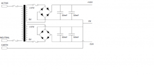
I'm currently using a 625VA ILP toroid with 2x 35V secondaries, 5% regulation. At the moment it's connected directly into the bridges, as shown in my circuit diagram hence each bridge handles 35V AC. If I connect as in your diagram, then only one bridge is needed and output is 0.9V higher but the bridge is connected to 70V AC.
I need a slightly higher DC output than can be obtained with this old 35V tranny and I want two independent transformers (as per the otherwise dubious Elektor advice - their 230V/40V transformer suggestion gives >60V in the UK). So the plan is to use 2x 240V/38.5V transformers, each with dual secondaries, each secondary driving its own rectifier. Maximal independence. Aiming for 55V nominal DC output.
I will install my 10A fuses between caps I think... providing the resistance is <20 mR.
I would have thought that rectifying AC to DC you multiply it by a factor of 1.414, as the AC voltage is RMS, AC being a sine wave. So by rights ~37 VAC when rectified i would have thought should give you ~52 V DC.
Therefore, to get a higher d.c. you would need a higher AC supply.
Therefore, to get a higher d.c. you would need a higher AC supply.
Last edited:
Hi Calpe - the new transformers will have a higher voltage AC secondary winding. Planning 38.5V instead of my current 35V. So then I would get approx 55V instead of approx 49V (at low load).Therefore, to get a higher d.c. you would need a higher AC supply.
DC = AC x 1.414 - 3.1V (using dual rectifiers)
DC = AC x 1.414 - 2.2V (using single bridge rectifier)
(Remember that transformer AC output at idle is typically 5-7% higher than at max load).
- Home
- Amplifiers
- Chip Amps
- My Q-Watt project