OK so I started looking at the Nuvotem 230V/2x 40V 500VA transformer used by Elektor (winding ratio 5.75:1). I think regulation on that unit is also pretty bad - about 7.5%. Assuming 2.74V fixed losses then max voltage at idle at 253V would be:
Max Secondary Voltage = (253/230) x 40 x 1.075 = 45.33V AC
After rectification & filters: (45.33 x 1.414) - 2.74 = 61.36V DC
Instead, I propose a 240V/2x 38.5V 432VA transformer (winding ratio 6.23:1). Regulation is promised to be <6%.
Max Secondary Voltage = (253/240) x 38.5 x 1.06 = 43.02V AC
After rectification & filters: (43.02 x 1.414) - 2.74 = 58.09V DC 😕
253V mains seems to be quite exceptional. I have always measured 240V +/-2V at home. So with this 2nd transformer I would get a nominal output of:
Nominal Secondary Voltage = 38.5 x 1.06 = 40.8V AC
After rectification & filters: (40.8 x 1.414) - 2.74 = 55.0V DC 😀
(Did I get that right?)
OK so I started looking at the Nuvotem 230V/2x 40V 500VA transformer used by Elektor (winding ratio 5.75:1). I think regulation on that unit is also pretty bad - about 7.5%. Assuming 2.74V fixed losses then max voltage at idle at 253V would be:
Max Secondary Voltage = (253/230) x 40 x 1.075 = 45.33V AC
After rectification & filters: (45.33 x 1.414) - 2.74 = 61.36V DC
Instead, I propose a 240V/2x 38.5V 432VA transformer (winding ratio 6.23:1). Regulation is promised to be <6%.
Max Secondary Voltage = (253/240) x 38.5 x 1.06 = 43.02V AC
After rectification & filters: (43.02 x 1.414) - 2.74 = 58.09V DC 😕
253V mains seems to be quite exceptional. I have always measured 240V +/-2V at home. So with this 2nd transformer I would get a nominal output of:
Nominal Secondary Voltage = 38.5 x 1.06 = 40.8V AC
After rectification & filters: (40.8 x 1.414) - 2.74 = 55.0V DC 😀
(Did I get that right?)
My calculations are a slight bit different, but I also must say that my calculations assume ideal components (no voltage loss in the rectifier and an ideal transformer). So it is safe to say that I'm looking at worst case scenarios 🙂
* Max sec voltage (40 volts sec):
253 / 5.75 = 44 volts AC
DC: 44 * 1.4 = 61.6 volts DC
* Max sec voltage (38,5 colts sec):
253 / 6.23 = 40.6 volts AC
DC: 40.6 * 1.4 = 56.8 volts
So I gues in real life situations even the 40 volts transformer will be ok.
But if you want to take it safe, you could opt for a transformer with a slightly lower AC output.
253 / 5.75 = 44 volts AC
DC: 44 * 1.4 = 61.6 volts DC
* Max sec voltage (38,5 colts sec):
253 / 6.23 = 40.6 volts AC
DC: 40.6 * 1.4 = 56.8 volts
This is the 'on load' voltage... off load is much higher depending on regulation(?)
If i'm not mistaken the Bridge Rectifier Elektor had in their BOM list was: -
It's a FAIRCHILD SEMICONDUCTOR GBPC3502 Bridge Rectifier Diode, Single, 200 V, 35 A, Module, 1.1 V, 4 Pins.
GBPC3502 - FAIRCHILD SEMICONDUCTOR - Bridge Rectifier Diode, Single, 200 V, 35 A, Module, 1.1 V, 4 Pins | Farnell element14
http://www.farnell.com/datasheets/2190594.pdf
Vf (Forward Voltage Drop, per bridge) - 1.1v (Max)
Popchops as you've seen it's Forward Voltage VF Max is 1.1V
GBPC3504W - FAIRCHILD SEMICONDUCTOR - Bridge Rectifier Diode, Single, 400 V, 35 A, Module, 1.1 V, 4 Pins | Farnell element14
http://www.farnell.com/datasheets/2209500.pdf
GBPC3504W - FAIRCHILD SEMICONDUCTOR - Bridge Rectifier Diode, Single, 400 V, 35 A, Module, 1.1 V, 4 Pins | Farnell element14
http://www.farnell.com/datasheets/2209500.pdf
Last edited:
BTW: The PS isn't overdimensioned, the amp can consume over 560W.
Pardon me for jumping in. I'm feeling triggered due to my complete set of PCBs and components for a stereo pair laying in my shelves and waiting to be completed 🙂.
Where did you get this power consumption number from? In the article, Elektor states the amp's output power along with it's efficiency. Thus the maximum DC power consumption can be computed to about 330 watts per channel. A 500 watts SMPS is rather convenient with this - and a very clever idea of delange's, btw.
As the maximum power dissipation of a class AB amp doesn't occur at full load, but at about 2/3rd of it instead, a 0.7K/W heat sink, as recommended by Elektor, might not be sufficient. I'd choose one with no more than 0.5K/W.
there is no overcurrent, or short circuit protection, and no clip protection.
trusting all that available power to a single pair of output transistors seems optimistic to me. why not add a few more power transistors in paralell ?
If the designer were me, I'd also provide overload protection - to any amplifier. So, this amp surely isn't intended for PA services.
Have a look at the SOAR rating of these Semelab power devices. I've never seen something better. So I'll trust Elektor here 🙂. They aren't easily to obtain, though.
Btw, adding one more pair would decrease heat sinking demands somewhat, but isn't feasible with the given PCB layout.
It fits also horizontally. Mount it on risers or with an additional 90° angle and that problem is gone.
I'd also say that. But with the given base plate's depth, the SMPS would get very close to the input potentiometer, which might cause RFI problems, and to all the other connectors, which might cause security issues. But, as the base plate still is a rather simple sheet of aluminum, it might be replaced easily?
Ah, while in progress in reading this thread, I see delange's progress in case building. The finished parts (wood, perforated sheet metal) need not to be ditched if case dephth is increased. Just slide the chassis backward, so that the heat sink is fully exposed. This would also increase it's efficiency a little bit.
Slow as a snail, but 1st stages of the wiring up
Personally, I'd not prolong the transistors' leads. They are very fast devices, and longer leads might cause stability issues.
40 V secondaries would give me 57V nominal (@ 240V) and worst case > 60V. And that's assuming a 240V primary. If it's the recommended 230V nuvotem then... way in excess of 60V in case of max mains supply (253V)
So Elektor advice doesn't really work in the UK. I think I will specify 2x 38.5V toroids and 240V primary. Fortunately I live across the road from a small substation so my mains always seems to be 240ish.
Have a look at the datasheets of the active components (besides the Vbe multiplier). Their maximum voltage ratings are 200V and more. So this shouldn't be of any concern, even if the rails exceed 60V a considerable bit.
Best regards!
Last edited:
Kay, the i.c. as well as the output transistors are at end of life, so once stock ends you'll only be able to get them whilst Farnell etc. have them in stock.
This is why some of us have purchased spares.
This is why some of us have purchased spares.
Attachments
Last edited:
Thanks, calpe!
Now I understand why I don't find them at Mouser's :-(.
Pretty strange that less than two years ago Elektor chose parts that soon had to become discontinued :-🙂-(.
Have to order some spares from Farnell as well - and hope they will ship to my country.
Best regards!
Now I understand why I don't find them at Mouser's :-(.
Pretty strange that less than two years ago Elektor chose parts that soon had to become discontinued :-🙂-(.
Have to order some spares from Farnell as well - and hope they will ship to my country.
Best regards!
Thanks, calpe!
Now I understand why I don't find them at Mouser's :-(.
Pretty strange that less than two years ago Elektor chose parts that soon had to become discontinued :-🙂-(.
Have to order some spares from Farnell as well - and hope they will ship to my country.
Best regards!
I bought some spare from a German on-line reseller but I can't remember their name. They still had some inventory.
But I guess lot's of inventory's are slowly fading away:
https://octopart.com/mg6330-r-semelab-19020560
https://octopart.com/search?q=MG9410-R
Elektor was looking to put some kits together again. I'm curious wheter they will find sufiecient stock. Shame because the Q-Watt is a great amplifier.
Elektor was looking to put some kits together again. I'm curious wheter they will find sufiecient stock. Shame because the Q-Watt is a great amplifier.
Do you know that for sure?
Some weeks ago they offered the Q-Amp kits in their online shop at a big discount, what made me think that they're going to discontinue these kits. At the moment the kits are available no more. Today I've learned the reason for that...
With reduced rail voltages, thus reduced output power, the output devices might be replaced by ON's or Fairchild's devices MJL3281/1302, MJL4281/4302, or even NJW3281/1302, which are the cheapest by far. Be careful: Due to their limited SOAR (in comparison to the Semelab originals), all these possible substitutes won't work (most probably will fail) at 55Vdc rails and 4 ohms. You'll need two pairs of these, at least. One pair might only be sufficient @8 ohms.
But the issue of the running out LM49811 still remains...
Best regards!
Edit: NJL3281/1302 pair removed from the list, as hese are 5pin ThermalTrak TM devices and not applicable here.
Last edited:
Do you know that for sure?
See the answer from Hedwig here (scroll down to the comments section): https://www.elektormagazine.com/labs/q-watt-simple-audio-power-amplifier-110656
I bought a couple spare transistors and a few LME devices as backup. I don't excpect them to fail easily but you never know...
Maybe Semelabs have some replcament parts for the transistors. I haven't looked at that.
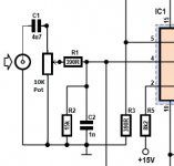
Many devices use a very high output signal today. The "standard" seems to have evolved to 2 volts for 0 dB. As you have seen in the specs, the Q-Watt amplifier input sensitivity is 0,88 volts for 137 watts (0.1% THD+N).
This means that you would need to use an attenuator in the chain in order to keep the amp in its safe area. That's why I have built in a potmeter to adjust the level (volume if you like).
If we do some more math, we'll see why Elektor chose this given voltage gain: For 220W @ 4 Ohms input sensitivity calculates to 0.771mV, which is very close to the standard 0dBV sensitivity (1mW = 0.775mV/600 ohms). For home use, I'll try to increase the value of both R1 and R3 to 510 ohms to achieve a sensitivity of 1V @ 220 watts. This requires some care, 'cause stability may be affected. Thus it demands some measuring tools (function generator, oscilloscope...).
Best regards!
Remember this project first appeared in Elektor in September 2013....electronics move fast....
T2 - MJE15032
https://export.farnell.com/Search?storeId=10152&catalogId=15001&categoryName=&selectedCategoryId=&langId=71&categoryIdBox=&st=MJE15032
1,113 will be available for delivery on May 25, 2017
1,050 will be available for delivery on Jun 9, 2017
1,450 will be available for delivery on Jun 28, 2017
T4 - MG6330-R
MG6330-R - SEMELAB - Bipolar (BJT) Single Transistor, Audio, NPN, 260 V, 60 MHz, 200 W, 15 A, 70 hFE | Farnell element14
No longer stocked
T3 - MJE15033
MJE15033G - ON SEMICONDUCTOR - Bipolar (BJT) Single Transistor, Audio, PNP, -250 V, 30 MHz, 50 W, -8 A, 30 hFE | Farnell element14
431 will be available for delivery on Mar 22, 2017
1,250 will be available for delivery on May 31, 2017
3,650 will be available for delivery on Jun 23, 2017
More stock available week commencing 10/07/17
T5 - MG9410-R
MG9410-R - SEMELAB - Bipolar (BJT) Single Transistor, Audio, PNP, -260 V, 35 MHz, 200 W, -15 A, 70 hFE | Farnell element14
No longer stocked
I.C. 1 - LME49811
LME49811TB/NOPB - TEXAS INSTRUMENTS - Audio Power Amplifier, AB, 1 Channel, ± 20V to ± 100V, TO-247, 15 Pins | Farnell element14
More stock available week commencing 03/04/17
Might be worth checking other suppliers e.g. RS Components, DigiKey, Mouser etc.
Last edited:
If we do some more math, we'll see why Elektor chose this given voltage gain: For 220W @ 4 Ohms input sensitivity calculates to 0.771mV, which is very close to the standard 0dBV sensitivity (1mW = 0.775mV/600 ohms). For home use, I'll try to increase the value of both R1 and R3 to 510 ohms to achieve a sensitivity of 1V @ 220 watts. This requires some care, 'cause stability may be affected. Thus it demands some measuring tools (function generator, oscilloscope...).
Best regards!
The 775 mv used to be a standard many ages ago. Today the standard is more like 2 volts;... all modern devices such as DAC's, CD players, etc output 2 volts @ 0 dB.
I prefer not to temper with those resister values because as you rightfully state that stability might be afected. It is a lot easier (and safer) to use attenuators. This way stability is not influenced.
Last edited:
As said before, I do not recommend tweaking the closed loop gain to everyone, especially not to those who don't own a precise square wave generator and an oscilloscope.
I'll ty it anyway. Maybe an attenuator will be demanded additionally.
Best regards!
I'll ty it anyway. Maybe an attenuator will be demanded additionally.
Best regards!
Popchops as you've seen it's Forward Voltage VF Max is 1.1V
Hi Calpe. I know the specs but I can't really explain why my DC is 2.7V less than AC x 1.414.
It must be 2x diode drops of approx 1V, and another 0.7V lost... somewhere... between the bridge rectifier and first capacitor.
Pops.
Do you know that for sure?
Some weeks ago they offered the Q-Amp kits in their online shop at a big discount, what made me think that they're going to discontinue these kits. At the moment the kits are available no more. Today I've learned the reason for that...
I don't think they will continue to sell them, they wouldn't throw them out if that would be the case.
Hi Calpe. I know the specs but I can't really explain why my DC is 2.7V less than AC x 1.414.
It must be 2x diode drops of approx 1V, and another 0.7V lost... somewhere... between the bridge rectifier and first capacitor.
That's exactly the reason. While it's often within the tolerance to ignore that on higher voltage power supplies, at such low voltages it's often a game-changer.
- Home
- Amplifiers
- Chip Amps
- My Q-Watt project