I used a miniDSP 2X4 HD.
You get the similar results with a passive LP filter..... cleaned up harmonics. And, that is the point.....
Now, its up to the circuit wizards to make LP filter with suitable performance level.
THx-RNMarsh
You get the similar results with a passive LP filter..... cleaned up harmonics. And, that is the point.....
Now, its up to the circuit wizards to make LP filter with suitable performance level.
THx-RNMarsh
Last edited:
I used a miniDSP 2X4 HD.
You get the similar results with a passive LP filter..... cleaned up harmonics. And, that is the point.....
Now, its up to the circuit wizards to make LP filter with suitable performance level.
THx-RNMarsh
Yes I can accept that a passive low pass cleans stuff up, but a miniDSP (or any other similar equipment)? That means your signal has gone through an ADC, then DSP-processed, then out through a DAC, lots of active stuff, and then all harmonics down to -130dB??
A tall order!
Jan
I used a miniDSP 2X4 HD.
You get the similar results with a passive LP filter..... cleaned up harmonics. And, that is the point.....
Now, its up to the circuit wizards to make LP filter with suitable performance level.
THx-RNMarsh
Thanks. That should tie me up for the next few years.
Congratulations. We are now all on an FBI watch list.
So how to interprete the last shot in #5975 then? I also find it very hard to swallow. I mean, wouldn't the filter itself generate appreciable distortion? Where is it?
Jan
Hi Jan,
An active SVF will very likely produce less distortion than the oscillator it follows, given the same op amps, given passive tuning or a fixed-frequency arrangement. Distortion should then be pretty much limited to that of the op amps.
Cheers,
Bob
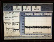
 1.5KHz filter on 100Hz signal
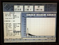
 150Hz filter
 While we are farting around about gain/scaling, which might be off by 10dB, from prior tests using QA401, here is another view of the distortion reduction using the Panasonic VP7722A, showing affect of filtering on 2H and 3H.
With this particular combination of filter characteristics (miniDSP HD/48db/oct) obtains a 20db or 10X reduction in distortion.
THx-RNMarsh
Last edited:
I wonder if you (or anyone else) has looked at Panasonic PPS SMDs ?
https://industrial.panasonic.com/ww/products-ec/smd-film-capacitor/smd-film-capacitor/echu/index
Patrick
Back to the ground 🙂
Panasonic PPS SMD 0805 10nF 16V from Patrick:
http://content32-foto.inbox.lv/albums/e/elterra/CapsC/1PanasonicPPS10nF0805.jpg
http://content32-foto.inbox.lv/albums/e/elterra/CapsC/2PanasonicPPS10nF0805.jpg
Unfortunately not the "high end".
Thanks Richard. That is impressive. The physicist/acoustician, mentioned to me that the MiniDSPs were better performer's than most people give them credit for, and sound better than most people who haven't tried them.
Infact those were his first solution for my speaker project...albiet one of the most costly.
For the amps suggest were around $1400 each I belive and I'd need two, then there is the
machining cost to place them in the speaker cabinets. These aren't your typical speaker
cabinets either.
So if all we want to do is clean up the signal...why not just a simple band pass
using high quality components?
Or
What is the issue with the B&K AND the active feature that was installed
for nulling better?
Why not do two active filters? One low pass and one high pass?
If someone doesn't need all the fixin's then we'd have all the parts
on the Symnet daughter board. That cuts the package to 1/3.
If we've got the power supply and other stuff taken care of
that could be it's own power supply. Someone can fold it over
like an EMU to make the box smaller and more useful and just
use it for higher quality parts right?
Scott, you mean those SHARC FPU processors aren't that good?
or is it in this application it doesn't do much good?
else the SHARC is better but MINIDSP FPU isn't
that great?
or what?
Back to studies.
The minidsp uses the Sigma Studio family of DSP chips. They are good and the digital pathway is 28/56 bit processing supporting double precision but the adc and dac are 100 dB class. You should not expect more for $7 or so. A good premium DAC.is better than that.
Do you really need continuous tuning at -150 dB distortion? Maybe 4 or 5 frequencies would be enough. A seperate dedicated box with source and notch connected to an analyzer would be relatively achievable and would avoid some of the difficult stuff.
Sent from my LG-H811 using Tapatalk
Do you really need continuous tuning at -150 dB distortion? Maybe 4 or 5 frequencies would be enough. A seperate dedicated box with source and notch connected to an analyzer would be relatively achievable and would avoid some of the difficult stuff.
Sent from my LG-H811 using Tapatalk
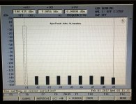
Affect of Band Pass Filtering
After I read what Richard has accomplished with
his work there I wanted to see what if, instead of
learning what diodes actually do.
Yes, I know those are the basics in my Solid State Devices...
...but really what are the affects of using Richards method
with this to see what it might look like...and being one for
simple too, hey, simple is good, but sometimes simple is
dis-eveing (spell check can't find it) too.
Why is it that way? For something to be simple in a complex
system it takes a lot of leg work and time to get to where things
are simple. So, it's taken me since my last post thinking, okay
I'll put up or shut up. Imagine that--me?
At first though, I didn't believe my eyes.
Cheers,
Sync
Post Script:
* = 2kHz
o = 3kHz
It's kind of funky the way it works, it is what it is. The symbols are so you
can ID two points, then zoom between them, or make other measurements
with them, add or subtract etc.
Attachments
Last edited:
The minidsp uses the Sigma Studio family of DSP chips. They are good and the digital pathway is 28/56 bit processing supporting double precision but the adc and dac are 100 dB class. You should not expect more for $7 or so. A good premium DAC.is better than that.
Do you really need continuous tuning at -150 dB distortion? Maybe 4 or 5 frequencies would be enough. A seperate dedicated box with source and notch connected to an analyzer would be relatively achievable and would avoid some of the difficult stuff.
Sent from my LG-H811 using Tapatalk
I was thinking if the miniDSP was that good, we could write some software for the DSP to generate test signals, sending them out through that -130dB DAC and get rid of all the other boatankers. 😉
Probably wishful thinking. ...
Jan
@Jan,
It just might be that good. Look at what I did with my boat anchor.
And that is based on a 30 year old anachronistic technology right?
Who in their right mind uses an IBM AT 'puter? What were those
chermans sinking, ja? Nicht Schlecht fur alte puter.
@everyman, Demian might be on to something also. So we have
the low oscillator, then we have a low box for them, then we have
Richards Proof, then my what if on Richards Proof, then wow,
it goes so low I don't think I can read it. So ADGR made the
4 box for Victors Oscilator, make four band pass 900Hz filters
centered around each of the four Fo - Bangholius
We Be Done - Done - Done!
Still for gear this old cranking out this kind of 1kHz, 1V sine....
Cheers,
Attachments
Last edited:
For david and others... here is an idea which could be updated and expanded.....regarding a sliding LP filter;
https://www.euetib.upc.edu/els-estu...nica-industrial/docs/datasheets/HA-2841_2.pdf
or
View attachment HA-2841_2.pdf
THx-RNMarsh
https://www.euetib.upc.edu/els-estu...nica-industrial/docs/datasheets/HA-2841_2.pdf
or
View attachment HA-2841_2.pdf
THx-RNMarsh
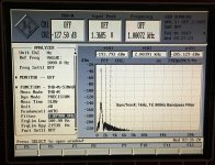
Here is the updated graphic, that wasn't saved.
Where the text is in the plot is about the level
of the noise floor....somewhere around -140dB.
😎🙂
-RNM
The minidsp uses the Sigma Studio family of DSP chips. They are good and the digital pathway is 28/56 bit processing supporting double precision but the adc and dac are 100 dB class.
This is the premium -HD model. Not using same as the other models.
THx-RNMarsh
Richard is there a possibility in the stock DSP software that lets you generate a test tone that you can look at after its DAC?
Jan
Jan
@Jan,
It just might be that good. Look at what I did with my boat anchor.
And that is based on a 30 year old anachronistic technology right?
Who in their right mind uses an IBM AT 'puter? What were those
chermans sinking, ja? Nicht Schlecht fur alte puter.
@everyman, Demian might be on to something also. So we have
the low oscillator, then we have a low box for them, then we have
Richards Proof, then my what if on Richards Proof, then wow,
it goes so low I don't think I can read it. So ADGR made the
4 box for Victors Oscilator, make four band pass 900Hz filters
centered around each of the four Fo - Bangholius
We Be Done - Done - Done!
Still for gear this old cranking out this kind of 1kHz, 1V sine....
Cheers,
Sure, but the fact that we cannot do much better than 30 years ago is in itself somewhat depressing, ja? 😱
Jan
Richard is there a possibility in the stock DSP software that lets you generate a test tone that you can look at after its DAC?
Jan
Not that I know how to do with it.
BTW - the spec is for -100dB for THD +N. With FFT = THD ?? 24b.
But better exists. I used a gen that had high enough harmonics to see the filtering effect. But an ultra-low distortion gen might be a harder thing to do a LP filter. However, I am sure it can be done.
-RNM
- Home
- Design & Build
- Equipment & Tools
- Low-distortion Audio-range Oscillator