In my country -one of the- vulgar proverb "the best one is to ....ing", but it is offtopic here. 🙂
There are many "the best" schematics.
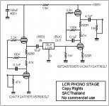
If I remember correctly, this schematic original was in Dave Slagle's forum:
:: View Forum - Phono
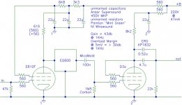
D3a as VAS, DC coupled 6N30P (russian 6H30) as CF (the another 6N30 half as active cathode load).
The output impedance only 41R!
Correct 600R loaded LCR, another AC coupled VAS stage with OPT.
If you don't like OPTs, try Aikidio.
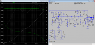
The attached schematic is only a simulation not your LCR RIAA?
Why ebay shows E810F and D3a like the same tube?
It'll work, according to the SIM plots, but for e180f, the grid is 0, for d3a is a bit on negative(?)
There is a capacitor in the path, since the plate voltage is low, should be direct coupled to 2nd stage IMO.
Attachments
Last edited:
Thanks Koonw.
But I still got it incorrect, regarding the terminating resistor R23, it can not be grounded as it'll carry DC current, therefore it's better to insert right after the plate of the 1st stage as DC will be blocked by capacitor C6. In the original sch you don't find 600 or 10k terminator I think, maybe pre-installed in lcr unit(?)
I now removed the terminating R23, and put C6 back as 100n as in original, the plot is stil quite flat. C6 and grid resistor R12, 1.5Meg are involved in 2nd stage output which now is a bit tricky..
Attachments
Last edited:
Yes it's installed in the EQ600 unit
If it exists, then you can not directly ground the terminating resistor(?), and an IT is in order to ensure LCR pad can be terminated properly without the DC or remove it for this sch to work.
There us a way to improve the schematic of Thorsten, for example using CCS, gyrator, etc?
No, because the first tube is a pentode.
Now try to figure out yourself why 😉
No, because the first tube is a pentode.
Now try to figure out yourself why 😉
More power, less distortion/noise?
More power, less distortion/noise?
With all respect Felipe, but it would be great if you had a keyboard without the "?"....🙁
It'll work, according to the SIM plots, but for e180f, the grid is 0, for d3a is a bit on negative(?)
There is a capacitor in the path, since the plate voltage is low, should be direct coupled to 2nd stage IMO.
Koonw,
E180F and E810F are completely different tubes.
Koonw,
E180F and E810F are completely different tubes.
Thank you for waking me up, I was looking for spice model e810f, end up getting wrong e180f model. There are no e810f model around, I now found 6j9p model, but I can paint one later.
If there no model for E810F, it is better to use spice model for D3a, it seems.
Ale Moglia (Bartola valves) shows that the model for Russian 6Z51P "close" to E810F.
If I remember well from old story about LCR RIAA; input tube should be strong to good drive LCR circuit in RIAA.
Best diying
Ale Moglia (Bartola valves) shows that the model for Russian 6Z51P "close" to E810F.
If I remember well from old story about LCR RIAA; input tube should be strong to good drive LCR circuit in RIAA.
Best diying
Thank RajkoM.
Now back to SIM. Now that I inserted after the plate a 9u cap C12 in series with 600R, R27, therefore do away direct grounding part. Checked that Silk LCR sch, you'll notice the connecting component is also a 10uf cap. so I don't see why this shouldn't work as well.
Now back to SIM. Now that I inserted after the plate a 9u cap C12 in series with 600R, R27, therefore do away direct grounding part. Checked that Silk LCR sch, you'll notice the connecting component is also a 10uf cap. so I don't see why this shouldn't work as well.
Attachments
With all respect Felipe, but it would be great if you had a keyboard without the "?"....🙁
Whitout "?" I lose my ADN😀
E810F model
.SUBCKT 7788/E810F 1 4 2 3
+ PARAMS: MU= 57 EX= 1.40 KG1=102 KP=200 ; KG2= 4500 kg2 isn't used, kg1 models overall gm
+ KVB= 8 VCT= 0.00 RGI=1000 ; kvb models plate resistance
+ CCG=14.5P CPG1=0.036P CCP=3.5P
RE1 7 0 1MEG
E1 7 0 VALUE= ; E1 BREAKS UP LONG EQUATION FOR G1.
+{V(4,3)/KP*LOG(1+EXP((1/MU+V(2,3)/V(4,3))*KP))}
G1 1 3 VALUE={limit((PWR(V(7),EX)+PWRS(V(7),EX))/KG1*1.57*ATAN(2*V(1,3)/(KVB*3.14159)),0,v(1,3)/710)} ; added limit-better models lower plate voltage limit condion
*G2 4 3 VALUE={(EXP(EX*(LOG((V(4,3)/MU)+V(2,3)))))/KG2} * this equation sucks
G2 4 3 value= {(I(G1)*39/(V(1,3) + 30))} ; this models change in current with change in plate first var changes ig2, second pushes right/left
RCP 1 3 1G ; FOR CONVERGENCE
C1 2 3 {CCG} ; CATHODE-GRID 1
C2 1 2 {CPG1} ; GRID 1-PLATE
C3 1 3 {CCP} ; CATHODE-PLATE
R1 2 5 {RGI} ; FOR GRID CURRENT
D3 5 3 DX ; FOR GRID CURRENT
.MODEL DX D(IS=1N RS=1 CJO=10PF TT=1N)
.ENDS
Thank euro21.
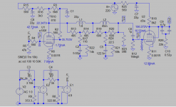
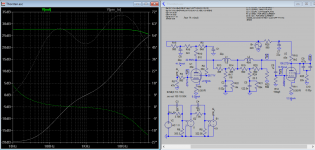
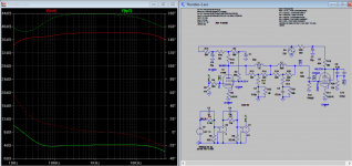
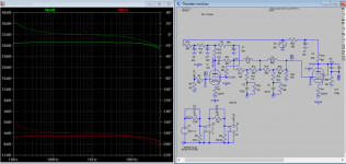
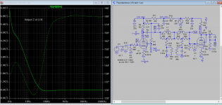
Now I have a few sim plots of LCR phono using E810F. It's a combined sch of zero bias of Thorsten and cap coupling of Thunderstone. I plot the input and output impedance at various test points to verify that they're technically correct, it's quite an exercise for me. Sonic wise you only know as you build it. Likewise I hope this help you to understand and raise appropriate questions. For example output impedance of input LCR driver has been raised so the combined Z is close to LCR input Z, do you agree?
Now I have a few sim plots of LCR phono using E810F. It's a combined sch of zero bias of Thorsten and cap coupling of Thunderstone. I plot the input and output impedance at various test points to verify that they're technically correct, it's quite an exercise for me. Sonic wise you only know as you build it. Likewise I hope this help you to understand and raise appropriate questions. For example output impedance of input LCR driver has been raised so the combined Z is close to LCR input Z, do you agree?
Attachments
-
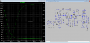
 LCR output Z SIM-6.png265.8 KB · Views: 198
 -
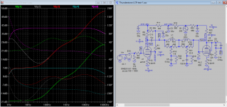
 LCR Z of U1 LCR combined SIM-5.png264.6 KB · Views: 204
 -
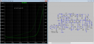
 LCR U1 Output Z SIM-4.png264.2 KB · Views: 195
 -
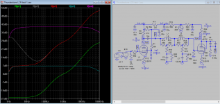 LCR freq Response SIM-3.png255.5 KB · Views: 682
 -
 LCR freq Response SIM-2.png287.9 KB · Views: 709
 -
 LCR Sch SIM-1.png266.8 KB · Views: 732
 -
 LCR U2 output Z SIM-7.png244.9 KB · Views: 228
note C13 10µ vs 100n ....
I noticed that. That 100n and 1Meg5 pairs or any others pairs is no where close to termination resistor of 600. If you think you can get away with it think again after you verify the impedance at each point, then you'll be surprised to see that the characteristic of 600 ohm LCR unit has not even properly utilized. I like to leave the verification to others to be meaningful if they have not done that already.
- Home
- Source & Line
- Analogue Source
- Looking for the best SQ Phono LCR schematic