thanks doctormord,
that all is taking a lot of your time. is it still set up?
if so please show plots with 24vdc!
.
Okay, were on my way to bed.
Very close to EVM board. Too close for the +30% inductor difference I found I think, you replaced them too ?
(edit laserdot clone here one inductor 11 and 11.05uH and other 12 and 12.45uH, one board two inductors with two different frequencies, so closer than Sanwu I mentioned earlier)
Just changed the IC.
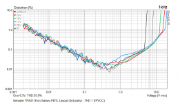
At 1kHz:

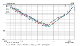
At 6kHz:

At 6kHz:
Attachments
Last edited:
At 1kHz:
i owe you doctor.
that is about 5w better than the generic.
i get about 50w 4r just before clip.
its really amazing they sound so good, the thd does not seem to be complete story with class-d on music.
thanks
Very close to EVM board.
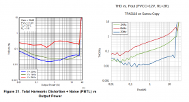
Compared to Fig. 21 in datasheet, performance is worse at 10W. (0.02% vs. 0.1%)
And the rest of todays measurements.
1W into 4R at 24V:

10W:

From the results, at 12V is "might" sound warmer, due to more K2.. But this is measured into resistive load.
That's 14.1Vrms - from the plot at 6kHz ~4% THD then.
1W into 4R at 24V:
10W:
From the results, at 12V is "might" sound warmer, due to more K2..
But this is measured into resistive load.i get about 50w 4r just before clip.
That's 14.1Vrms - from the plot at 6kHz ~4% THD then.
Attachments
Last edited:
Fig.7 is 4 ohm, but btl, 21 is 2 ohm pbtl 🙂Compared to Fig. 21 in datasheet, performance is worse at 10W. (0.02% vs. 0.1%)
I disagree, TI shows you 6 ohm outputfilter with 2 ohm load, or 4 ohm. Take a look what happens from around 2 kHz with overdamped filter
Take a look, 0.1% is 1/1000th, adjust your scale. PBTL has slightly higher distortion than BTL.
70w 4r with 28V . perfect !
I take onset of clip and divide by two.
That would be the rating for hi-fi. 35W 4r. in PBTL mono bloc.
Risky at 28v, maybe not?
Great work.
.
I take onset of clip and divide by two.
That would be the rating for hi-fi. 35W 4r. in PBTL mono bloc.
Risky at 28v, maybe not?
Great work.
.
Take a look, 0.1% is 1/1000th, adjust your scale. PBTL has slightly higher distortion than BTL.
And? The measurement is more worse anyway.
The board is PBTL so i compare with PBTL figure. 2R will have more distortion than 4R. But even so, the EVM is "better" at 2R. To me, the measurement is not quite close to EVM.
Things might change with different inductors.
70w 4r with 28V . perfect !
I take onset of clip and divide by two.
That would be the rating for hi-fi. 35W 4r. in PBTL mono bloc.
Risky at 28v, maybe not?
Great work.
.
70 Whot? 😀
Yeah with 4+% THD. 😀
28V was no problem but wouldn't say it's stable with 2R very long. Caps are rated for 25V only, 28V is usually the surge limit. At 30V the chip ***** down immediately, even without signal. (OVP i think)
Last edited:
28V at chippins? or befor diode at input? What is diodedrop at 10W ?
TI BTL graph 4 ohm fig 7 shows higher distortion than PBTL 2 ohm fig 21, TI support mentioned with same load BTL has slightly lower distortion than PBTL. Difference graphs is more overdamped filter.
TI BTL graph 4 ohm fig 7 shows higher distortion than PBTL 2 ohm fig 21, TI support mentioned with same load BTL has slightly lower distortion than PBTL. Difference graphs is more overdamped filter.
32dB, filtervalues, unequal much weaker inductors
Layout I now suspect to be superior even to EVM, I never thought that was really possible 🙂
Layout I now suspect to be superior even to EVM, I never thought that was really possible 🙂
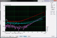
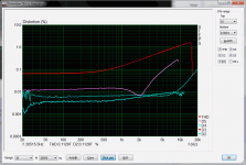
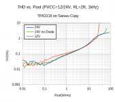
Bridging the diode didn't made any relevant difference. Test at 24V is limited by power supply. (24V 5A)

From datasheet, at12V and 2R -> 33W (1% THD) should be possible, we got 25W, okay.
NOTE: The "24V nodiode" plot is done with higher integration time, as the "24V" plot is a bit suspicious at higher power levels.
Yeah, inductors are having the biggest influence, they're pretty much undersized. (At 12V and 25W into 2R it's "okay).
From datasheet, at12V and 2R -> 33W (1% THD) should be possible, we got 25W, okay.
NOTE: The "24V nodiode" plot is done with higher integration time, as the "24V" plot is a bit suspicious at higher power levels.
32dB, filtervalues, unequal much weaker inductors
Layout I now suspect to be superior even to EVM, I never thought that was really possible 🙂
Yeah, inductors are having the biggest influence, they're pretty much undersized. (At 12V and 25W into 2R it's "okay).
Attachments
Last edited:
- Home
- Amplifiers
- Class D
- Cheap TPA3118D2 boards, modding them and everything that comes with it