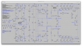
I see variables in your schematic but I cannot tell what values you chose. ??
When multiple parts have the same value and we need to change them all together, it makes it easier to make the value a parameter and change only that instead of each part value one at a time.
The values in the parts this have a variable name instead of the value, and the variables are defined separately with a .param statement, which is in an other place but still in the schematic.
I usually try to keep related variables to parts fairly close, but when the parts are spread out, it's not quite that obvious.
In the case of the ltp stages, I placed the variables together in the middle.
I can then switch more easily between those values, either change them directly, or make several instances and rem out the ones not in use at the time.
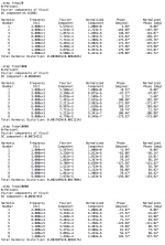
But for certain thing, we can also "step" through the values with the .step statement. This is what I've been doing to obtain results on 4 frequencies in one simulation instead of running 4 separate simulations and changing values each time manually.
I find it very interesting that not changing the topology, just changing parts values, can have this effect at this late stage. The initial component values chosen were safe starting points but not optimal. I assumed we were close to optimal values, but obviously there is room for improvement. Rather than me proposing changes via schematics, feel free to tweak this.
I have occasionally done such changes, such as the compensation caps for example.
Some changes have repercussion on other things, which require changing other values somewhere else to keep things about the same (bias), so it's not always a single easy change.
We can step through pre-established values, but when those impact other things, it can get tricky.
I'm reminded of operations research, in which optimums are chosen by finding points where the derivative of some function is zero, presumably at a peak or valley. But it could be a saddle, in which case you test by random walks to verify that the supposed peak is not a saddle. That is not directly applicable here, but perhaps the concept is, that is, to test that our design is optimal by varying component values within limits.
Actually it is applicable here and I have encountered such a saddle situation, when I explored the values of the big filter caps.
We do have such an effect there, where there is an optimal value and more or less than that value isn't as good.
Stepping through values and plotting that can be quite interesting, but it's not always that easy to do though.
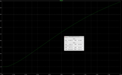
My case in point is this latest variation of minutiae, the emitter resistors and collector loads. It turns out that slight changes can make dramatic improvements. I hope we are not overlooking other such cases.
We've gone through so many things, I think there aren't too many more avenues to explore. We can probably find a few values to tweak further, but we also must keep in mind that real parts don't have accurate values, and this implies selection and matching.
Personally I would always attempt to do as much selecting and matching for the best possible result.
In this amp, I think it's a must to match the active parts the best we can, and while at it, why not some of the important passives as well?
The big caps have such a wide tolerance, that I think it mandates measuring them and match them the best we can.
The values we use in the simulations are exact, and we find that for some values, a small change can have serious implications, so either use expensive (or rare) parts with very tight tolerances, or simply use good parts but cheap with loose tolerances and select them. For many parts, the cost saving from not using the expensive tight tolerance types can easily pay for the measurement devices.
When we use a good ohm meter, why bother buying 1% or even 0.1% parts, when the 5% or 10% could do fine, when they are measured and matched?
In the past few years, I have added a few cheap measuring devices to my poor panoply, to measure capacitors, resistors, etc... and I didn't spend much. A meter doesn't even have to be super accurate, as it's not always so much the actual value that needs to be exact, but rather the matching between parts. Any cheap meter can allow that. Why not rolling up the sleeves and do it? I would!
Good, and hopefully we maintain stability.
My last adjustment kept that under control. I wish we could do a proper phase/gain margin analysis, but we can't, as far as I can tell, and so far nobody has come forward with anything to accomplish this.
The downside of reducing the emitter resistors is more sensitivity to poorly matched input transistors.
Matching is a must, for the transistors, for the resistors, and some caps.
Those big filter caps must be matched. They are top important, just as much as the ltp transistors.
Choosing the right kind of input cap is also something to do carefully.
We may have to hand select these, since the makers are dropping matched pairs.
I think there is no way around that. But for the low signal parts, we don't have too much to worry about, as they're still available and they're cheap, so why not get a big batch and select them carefully?
It would be more expensive to do the same for the power transistors, but I think it's worth some effort. Perhaps having an online community can help with this, because someone could do the matching, from a group buy of parts, which would draw from a much larger batch for better part matching.
I have a few in my parts drawers, but I can't use them for new design because the supply is uncertain.
Which ones are those? The BCs? Those are no problem to get, even today.
Even those BD139/140 are still easily obtainable.
We haven't used any really exotic parts during the design process, so I don't think we need to worry much about finding parts.
Personally I think I probably have most of the active parts, except perhaps for the diodes, but their choice isn't so critical anyway.
I keep a good amount of what I have in my stock in a spreadsheet so I know what I have handy, and I just double checked and I do have a bunch of the MJL21193/4, the MJE15032/3, the BD139/140 and I may even have some BC550/60 somewhere.
As I said before, please tweak this yourself if you sense an opportunity for improvement. As for me, I would like to see what 1k/47 yields. Only at 20khz perhaps?
Easily done, we'll look at that, and since it's set up to step through 4 frequencies, we get all that every time for easy comparison.
Is the VAS the next area?
Sure, why not? But this vas has seen many incarnations already, so we've been able to compare quite a bit, but there is likely more to do there.
We have one other thing we can explore, the cascoding of the drivers as suggested earlier.
This amp is turning out pretty nice already, if we go with the latest that had the best results, we're in the neighborhood of around 40ppm of thd, or less, which ain't bad, for a capacitor coupled amp...
Not bad at all with 1k/47.
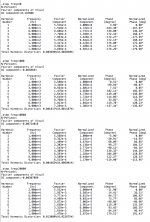
We're at less than 40ppm thd across the board, and the highest is at 20hz, which can be improved a little by tweaking the big cap value and probably a bit the input filter cap as well.
I kept the clamp diodes disconnected, but just to see their impact, I'll run this again with them reconnected.
And then we'll take a look at noise and slew rate.
Attachments

I would stick with the BC550C (and complementary), especially the C suffix for highest gain:
http://eu.mouser.com/ProductDetail/...=sGAEpiMZZMshyDBzk1/Wi4G1GLBZKHK1PoBUNRlzER4=
http://eu.mouser.com/ProductDetail/...=sGAEpiMZZMshyDBzk1/Wi4G1GLBZKHK1PoBUNRlzER4=
Here's something that may be of interest.
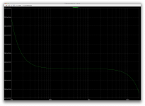
Just to see how much noise contribution was coming from the current sources, I used ltspice ordinary current source and disconnected our discrete ones.
And conclusion: our current sources don't seem to be contributing any noise at all.
Now that's unlikely to be the same for the mirrors, but at least we know there is nothing we can do to the sources for better noise performance.
And as far as thd is concerned, using those more perfect sources only brought thd down by barely 0.2ppm, which is nearly nothing, so they are real good as they are now.
Attachments
Last edited:
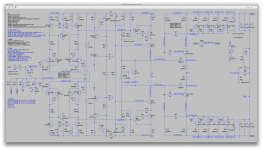
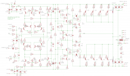
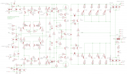
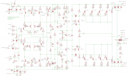
So, I am adopting 1k/47 as standard. I deleted the cascode on the current source. I deleted the Schottky's. The fact that the Schottky's had any effect, albeit negative, implies that the current mirrors do indeed saturate, not so good, but we will defer looking at that.
I added a load resistor across the LTP, which is suggested for stabilizing the VAS operating point by providing a defined load for the LTP/mirror. I'm not convinced, but let's try it.
I changed the VAS input transistor to BC5X0, for reduced Ccb. I prefer the 2n4401 here, but Self claims that there is marked improvement using lower capacitance parts. Once again, try it and we'll know. I also changed its collector load based on what we just learned, hope nothing unexpected arises.
I toyed with changing the BD parts, but later. We need the dissipation capability, at present currents. We have to supply the MJE1503x driver bases with significant current, and these commonplace parts suit that. If we can reduce the standing current and drive requirements, I may try something like 2n440Xs here, for better HF behavior. Later.
Attachments
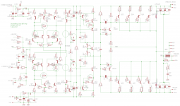
This idea of cascoding the driver is interesting. It's not without issues. Here are two attempts.
I'm hoping someone will suggest a good candidate for the BJT drivers. Can use MJE1503X as standins for now.
In the mosfet version, the 640 is massive overkill but I found it in my eagle library, so here it is. Any 200v part with modest (6A) current capability suits if you have it in your library. Even 240s would stand in. I think the cascode topology is what matters, not the exact part.
Attachments
Spookydd said: Just to see how much noise contribution was coming from the current sources, I used ltspice ordinary current source and disconnected our discrete ones.
And conclusion: our current sources don't seem to be contributing any noise at all.
...
And as far as thd is concerned, using those more perfect sources only brought thd down by barely 0.2ppm, which is nearly nothing, so they are real good as they are now.
I say: I removed the cascode on the current source as it did almost nothing. You have been modeling with it in. I hope we won't miss it.
So, I am adopting 1k/47 as standard.
Sounds fair. It works best that way so far.
I deleted the cascode on the current source. I deleted the Schottky's. The fact that the Schottky's had any effect, albeit negative, implies that the current mirrors do indeed saturate, not so good, but we will defer looking at that.
Wouldn't the saturation cause non linearities? I assume if something was wrong there, that any induced non linearity would be reflected in worsening thd.
Before running this new sim with all the changes, I started deleting the cascode only and ran it. And indeed the cascode doesn't bring anything there. It's certainly not hurting anything, but without it the noise and thd are the same, so no need to keep the extra complexity there.
I added a load resistor across the LTP, which is suggested for stabilizing the VAS operating point by providing a defined load for the LTP/mirror. I'm not convinced, but let's try it.
This however doesn't seem to bring anything good and causes a thd rise (and not a small one).
It was taking a longer time than usual to find the operating point, and then running the stepped transient sim with 4 frequencies was taking so long that I just ran it at 1khz.
I changed the VAS input transistor to BC5X0, for reduced Ccb. I prefer the 2n4401 here, but Self claims that there is marked improvement using lower capacitance parts.
That's possible, and the higher gain may be of help there, but first before we see if there are benefits from that, we should address the issue I mentioned above. I don't really think those different parts are the cause of the thd rise. I suspect more that extra load between the ltp legs (maybe).
Once again, try it and we'll know. I also changed its collector load based on what we just learned, hope nothing unexpected arises.
Only a harder to reach operating point and much higher thd. Maybe a little tweaking might fix this.
I toyed with changing the BD parts, but later. We need the dissipation capability, at present currents.
Having them cascoded helps with dissipation, with the load sharing.
By curiosity to check where we stand on this dissipation as it is now, I checked it on each BD part, the vas BD dissipates about 165mW, while its cascode mate dissipates about 228mW. Well within their capabillities, but they should be heatsinked.
We have to supply the MJE1503x driver bases with significant current, and these commonplace parts suit that. If we can reduce the standing current and drive requirements, I may try something like 2n440Xs here, for better HF behavior. Later.
Perhaps we could take a look at those MJE340/50 as well.
Attachments

This idea of cascoding the driver is interesting. It's not without issues. Here are two attempts.
I'm hoping someone will suggest a good candidate for the BJT drivers. Can use MJE1503X as standins for now.
In the mosfet version, the 640 is massive overkill but I found it in my eagle library, so here it is. Any 200v part with modest (6A) current capability suits if you have it in your library. Even 240s would stand in. I think the cascode topology is what matters, not the exact part.
It seems premature to try this out with the previous changes that aren't quite up to par for now.
Perhaps it might be better to try this out on the previous implementation that was known to work well and was performing nicely.
I'm not sure I have good models for the irf640 type parts. That will have to be tested. I don't usually do much with fets in audio, and I'm not certain about the models quality.
I wonder if something like this could be used:
http://www.nxp.com/documents/data_sheet/PSSI2021SAY.pdf
It's SMT, but maybe something not SMT exists.
Would something like this be better performing for current source?
http://www.nxp.com/documents/data_sheet/PSSI2021SAY.pdf
It's SMT, but maybe something not SMT exists.
Would something like this be better performing for current source?
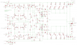
Spookydd said: This {LTP collector load resistor} however doesn't seem to bring anything good and causes a thd rise (and not a small one).
I say: The load resistor goes. Its sole purpose of providing a defined load to the LTP/mirror is probably already accomplished by the 180k/33k bias resistors on the VAS. These serve other purposes, but they incidentally provide appropriate bias here too. So the load resistor should go.
Regarding the VAS, I am curious if just changing the BC input transistor did anything good. I am curious if changing the 1k collector load was beneficial.
Is is possible to change each one independently, just for comparison? If we change both together, we can't see the effect in isolation. Meaning, keep the original 2n part, change the resistor. Then keep the original 2k2 part, change the transistor.
VAS Current: I mentioned that we might be able to reduce distortion in the VAS by reducing current. At present, this is 30ma standing current, but the drivers consume less than 1ma at idle. Reducing this gives us more options for choosing lower capacitance parts.
So, let's try reducing VAS current. This reduces gain at the VAS too, so what is the net effect?
Attachments
The load resistor goes. Its sole purpose of providing a defined load to the LTP/mirror is probably already accomplished by the 180k/33k bias resistors on the VAS. These serve other purposes, but they incidentally provide appropriate bias here too. So the load resistor should go.
It was worth trying, and we're simulating, which costs nothing to try out whatever we want, so why not indulge? 🙂
Regarding the VAS, I am curious if just changing the BC input transistor did anything good. I am curious if changing the 1k collector load was beneficial.
Is is possible to change each one independently, just for comparison? If we change both together, we can't see the effect in isolation. Meaning, keep the original 2n part, change the resistor. Then keep the original 2k2 part, change the transistor.
Sure, we'll try out each possibility for proper comparison.
I have some other work to do at the moment, but I'll get on this shortly.
VAS Current: I mentioned that we might be able to reduce distortion in the VAS by reducing current. At present, this is 30ma standing current, but the drivers consume less than 1ma at idle. Reducing this gives us more options for choosing lower capacitance parts.
So, let's try reducing VAS current. This reduces gain at the VAS too, so what is the net effect?
Sure, we've had that current much lower several times before. Recently we had it down around 17-18mA, and that was fine as well.
We can probably do fine with perhaps in the 15mA range, to keep it beefy enough so the needs of the drivers remains little in comparison.
Cutting that current in half would be good enough for lower dissipation.
Once we finalize the topo and other values, we'll look much more closely at the dissipation, in each part.
Spookydd said:
We can probably do fine with perhaps in the 15mA range, to keep it beefy enough so the needs of the drivers remains little in comparison.
I say: We can go 15, but try 10ma so we can test low Ccb transistors.
We can probably do fine with perhaps in the 15mA range, to keep it beefy enough so the needs of the drivers remains little in comparison.
I say: We can go 15, but try 10ma so we can test low Ccb transistors.
Regarding the VAS, I am curious if just changing the BC input transistor did anything good. I am curious if changing the 1k collector load was beneficial.
Is is possible to change each one independently, just for comparison? If we change both together, we can't see the effect in isolation. Meaning, keep the original 2n part, change the resistor. Then keep the original 2k2 part, change the transistor.
VAS Current: I mentioned that we might be able to reduce distortion in the VAS by reducing current. At present, this is 30ma standing current, but the drivers consume less than 1ma at idle. Reducing this gives us more options for choosing lower capacitance parts.
So, let's try reducing VAS current. This reduces gain at the VAS too, so what is the net effect?
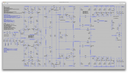
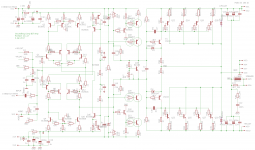
Ok, to make comparisons meaningful, I'm starting from a previous known working config and I will independently change those parts. Then We'll see how a reduction of the vas bias affects things as well.
One thing to keep in mind with the cascode (on the vas), is that it can be taking the brunt of the voltage swing and dissipation, while the vas transistor being shielded somewhat by its cascode companion could be a high gain low cob and lower vce part. We should easily be able to use the BC550x or whatever, instead of the BD parts, especially if we do reduce the vas bias, the dissipation there should be well within the capabilities of a non heatsinked TO92 part or similar. The bulk of the dissipation can happen in the cascode.
I'm posting the config with the 2N440x and the BD parts, with the 2k2 and 47ohms vas load, to use as the reference with the next configs with each part changed. This should make the comparison easier.
None of this stuff should affect the noise figures, so there is no point in cluttering the results with that.
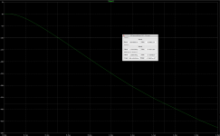
And by the way, a lot of the noise in the ltp stages is a function of the tail current, as well as the values of the resistors that set the gain (feedback, input filter...)
We've tweaked this already and it's a tough compromise, as this affects also the input impedance and a few other things. But the lower those resistor values, the lower the noise figure. And of course, the lower the tail current, the lower the noise.
So many compromises.
I will also post something interesting shortly. I just ran a simple sim on a dual ltp similar to what we're using, just to see what the effect of the degeneration resistors is on the ltp, and see how much linear range we can expect with different degen res values. This result speaks volumes.
Attachments

- Status
- Not open for further replies.
- Home
- Amplifiers
- Solid State
- grounded collector amp