We need to step back to a known working configuration. As near as I can see, the two recent changes were changing the power filter R from 100R to 33R, and changing the VAS emitter resistor from 100R to 47R.
I would suggest undoing the first, revert to power filter R of 100R. Verify operation.
If that is not working, revert to VAS emitter resistor of 100R.
I didn't think the power filter res would affect this, but here it is. Unbelievable! The abrupt behavior vanished and it adjusted fine this time. The only change made is the 33 back to 100.
Of course it changes the operating point position quite a bit, so perhaps that behavior may happen at some other point, but not where we need it to operate.
I'm curious to know what causes this.
Attachments


All of the devices we're using for the simulation can be easily procured, and the small signal and even the vas parts are cheap, so it's not much to grab large batches and do part selection and matching.
It might be worth comparing the MJE15032/3 with the 34/5 eventually. I've seen those available, perhaps not as easily, but doable, and I did notice differences in simulations before with those.
I tend to stay away from exotic parts such as the japanese ones, because they are not always so easy to procure, especially in some areas on this planet.
Some japanese parts are also made by us based manufacturers and perhaps could be compared. I'm thinking about for example the ksa1381 from fairchild, being their version of the 2SA1381, and it's 3503 complementary. Those are often used for vas...
It might be worth comparing the MJE15032/3 with the 34/5 eventually. I've seen those available, perhaps not as easily, but doable, and I did notice differences in simulations before with those...
Higher Vce, but only half the Ic ratings, compared to MJE15030/31 or MJE15032/33, respectively? Best regards!
Higher Vce, but only half the Ic ratings, compared to MJE15030/31 or MJE15032/33, respectively? Best regards!
True. But we're far from using all that.
Anyway, I was curious and tried them just to see, and nothing good came out of it, so our current selection works great.
Any other possible to try?
I did try the KSA1381/KSC3503 instead of the BD139/40, and that too wasn't conclusive. I thought the higher gain would help, but it didn't.
I just tried just for kicks, the MJE340/50 instead of the MJE15032/3, and I had to adjust compensation (only the global feedback) to cure oscillations that showed up, and even after stabilizing it, I also had to slightly reduce the input level, as for a weird reason, it was exhibiting a little bit of clipping behavior at the negative side. Lowering the input level a bit cured that, but then thd was still far higher than with our current choices. Not good. What we have now works very nicely.
On our latest working version, I looked at what we have for dissipation in the outputs and how much vce swing we have.
Since they all are seeing the same thing, I only looked at Q11.
One thing I've been wondering is why we haven't been able to get closer to full swing near the rails, for maximum output power. I suspect the clipping isn't happening there on the output but probably on the vas first.
The clipping looked fairly well behaved though, when we didn't have oscillations.
Anyway, looking at Q11, we don't get below about 3.4V on its emitter, and the max vcesat for the mjl21193 is listed at 1.4V for Ic 8A, which we're not reaching (less than half that), so obviously we're not saturating the outputs, and thus they're not the ones doing the clipping.
Because of this, we can see the vce swing is only about 112V and the devices are exposed to only about 115V of max vce.
For power dissipation, we reach a peak power near 55W, so we're very well within limits, and the average dissipation about 17W (per device).
That was at 1khz on the resistive 4ohms load and full nominal output power a tiny bit before clipping starts.
If I remember right, this isn't the maximum power dissipation, which happens at 2/3rd the output power (Am I correct on this? Or is this at half power?).
17W times 8 devices, 136W of average power to dissipate on the main heatsink, not including the small amount from the drivers.
So as long as we use a heatsink that has less than 1 degreeC/W of thermal resistance, this should work out well.
Having no need for insulators on the output devices removes a good amount of thermal resistance from the assembly. Demanding a smaller heatsink.
I think the MF20-1F-75 model from conradheatsinks would be nice for this:
Conrad Heatsinks - Products
With only 0.6C/W of thermal resistance, it should keep all this cool enough, and 20cm of flange length is probably enough to fit all 8 outputs plus the drivers and the sensing bias spreader transistor.
That would make a layout with all the power devices on on edge of the pcb, but that's quite common.
Attachments

To look at dissipation a little closer, I made that sim run steps at 1/2, 2/3 and full power.
We can see at the same time how the thd evolves at different power levels.
As I thought, the max dissipation is at 2/3 power, and 1/2 power dissipates more than at full power.
The difference isn't really huge but significant enough to take into account.
But that's a little more than 22W per output device total average dissipation.
176W, plus a little from the drivers, let's say we must evacuate some 180W of heat. With that 0.6CW sink, it's 108C of rise, plus let's say 25 ambiant, we're below the limit for the drivers (150C), but they don't dissipate so much themselves. The heatsink shouldn't get too hot.
Maybe an even smaller sink could be used.
If someone wanted to make a forced ventilated tunnel, it could be quite small.
Attachments

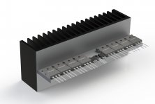
I'm sharing a visual I just made up.
I was wondering how everything would fit on the heatsink if using that model from conrad that I posted about earlier.
The size isn't very large and I wondered if all the devices would fit if everything was on one side of the pcb.
With 8 TO-264, 2 TO-220 and 1 TO-126, that's a fair amount to squeeze in that small space.
And although it would be tight, it would fit.
Of course that's just one possibility among many, but I thought I'd share my idea.
I looked at some small tunnels, a lot more compact, but perhaps too compact and I'm not sure how the devices would be bolted on them..
Attachments
I didn't know about those. But I don't have any models and couldn't find any after a quick search. Maybe someone can share their models, but we've tried others before and found that using those slower ones worked better. Those could be faster and cause the same issues we've had before. But worth trying, if models can be found. We never know.
Cost would need to be compared as well.
Due to their extended SOAR ratings the total of power devices could be reduced to three, or even two, pairs?
Not sure they would be that much better at this, but we chose 4 pairs somewhat arbitrarily, as we haven't even done any soa checking yet.
Once the schematic gets finalized and devices choices frozen, that would be next, all that stuff about dissipation and soa would be checked.
Amazing the large disparity of pricing between suppliers!
Anyway, overall, those would likely be much more expensive than our current selection.
But who knows? We can try them out, if we can get models. If there is a real difference, maybe it could be worth something, if that different is significant enough. Maybe those parts could be more easily available to some hobbyists, depending on where they are. As some people have a hard time finding parts that are easy to get elsewhere.
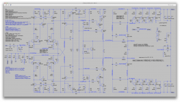
how about a refresh on the .asc so people can stay in sync, avoid hand mod/rentry errors?
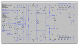
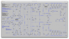
Sure. I hope I gathered all of the pieces so it can run right out of the box.
Attachments
Hi spookyd, the cause for me to suggest these devices to you was the not really ample space on your 200 mm wide heatsink. I know them, because in 2015 Elektor used them in their Q-Watt amplifier design - only one pair of them for 200 watts output power @ 4 ohms! Correct, these Semelabs maybe hard to find, e.g. in Germany, as RS Components *afaik* do not sell to private users anymore and the other suppliers from the Octoparts lists are not active here. OTOH, the SOA ratings of these MJL21193/94 aren't too bad, too, with 3.5 amps@50 volts Vce. Hence, three pairs of them would be sufficient, I think. Best regards!
Hi spookyd, the cause for me to suggest these devices to you was the not really ample space on your 200 mm wide heatsink.
Well, that heatsink idea is just one possibility among many. I wasn't suggesting it has to be that one specifically. I just thought it would be a good one that's all.
And besides, I did take a closer look at those MJL devices and there exist a "flavor" in a TO-247 case instead of the TO-264, which is slightly narrower.
So eventually if space was to be an issue, the TO-264 version could be easily swapped to the TO-247 one, since the devices are electrically virtually identical, with the case being just about the only difference.
Still, that cad drawing proved it actually does fit, although tightly, it does work out fine.
The only devices that require an insulator on the heatsink are the drivers and the bias spreader sensor, so it's rather simple and efficient, and that insulator would be quite small and common to all 3 of those devices, which are grouped to make this easy.
the SOA ratings of these MJL21193/94 aren't too bad, too, with 3.5 amps@50 volts Vce. Hence, three pairs of them would be sufficient
Possibly, and when we take a closer look at our soa situation, we may even find we're over-built a little, but better be on the safe side and make it more robust.
In the simulations I use a 4ohms resistive load but not because we're aiming for such a nominal load, but rather to be in a worst case condition for any possible 8ohms load, with whatever reactive component it may have.
Instead of complicating the sims with complex loads that simulate some multi-way passive xover speakers, I just drop the load to 4ohms, which would never happen with any normal 8ohms speakers.
That way we cover any worst case scenario and keep it simple.
As long as the amp handles 4ohms resistive properly, it should be able to handle whatever 8ohms complex load we throw at it.
So when we look at dissipation, we're being super conservative, as a worst possible scenario. The reality is highly likely to be much less demanding, and actually the thd readings we have would also be better in reality.
When I threw that heatsink assembly together, it was just to confirm that it could be done that way, as I had some doubts because I knew it would be tight.
I like those sinks from conrad, with that lip that's part of the sink, we can design the pcb to be directly attached to it, making mounting quite easy, compact and we can also design the pcb in a way as to avoid as much wiring as possible, by putting input signal plugs on the board, and most of the power supply stuff as well, perhaps having only the transformer's wires left to hook up..
I don't like the forests of wires, and with power amps, whatever can be avoided as wires is a plus, I think.
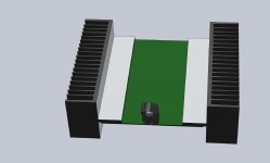
Just for illustration, I'm showing a concept based on those same conrad heatsinks, that I came up with for a grounded bridge build that we've worked on. Hopefully we'll get that one finished some day.
But just to show what could be done, here's a simple drawing.
That drawing shows 2 heatsinks, because that was aimed at having 2 amps on the same pcb, to make a grounded bridge.
All on a single pcb, including input plug, filter caps, rectifier bridge, just about everything except the big transformer (preferably a toroid), so since the heatsinks are only 75mm tall, the casing would have to be a little more roomy to allow fitting the big transformer and enough headroom for the big filter caps.
Other than that, the wiring left would be the transformer to the pcb and the speaker output, that's it, no other loose wiring.
That amp was based on the 2N3055, so the layout was for a bunch of TO3s, but it would work out the same for TO-264, TO-247, TO3P or whatever...
This kind of "packaging" is rather compact, simple and makes for fairly small mono-blocks that can be put anywhere, especially real close to speakers, if not made part of the speaker boxes.
With a single heatsink, that layout can quite easily make it possible to include inside a speaker box, leaving the sink ventilated naturally on the backside.
Attachments
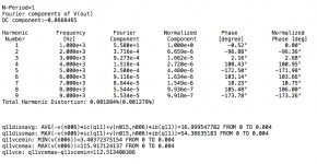
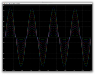
I ran a sim at 1khz and stepping through values of input levels to see how the thd evolves.
I'm a little surprised at the lowest input levels to find that thd increases this much.
We have a plenty generous bias current, and I would expect low levels of xover distortion, but perhaps this increase is coming from some other mechanism, perhaps the capacitors, input or filters.
I ran it with 100mV increment, and this gives 14 data points, which is a little too much to post as a screenshot, so I just posted the log file, with extension txt to make it easier to read as is.
The thd is a little higher than expected at the lowest levels, then diminishes nicely, and slowly and gradually increases with the higher levels, up to clipping, where it starts increasing much more, as expected.
Attachments
I've been working on getting plots to check for SOA and I was considering using out friend astx's perl script to make things easier. He wrote his script to automate making plot files to make it easier. His thread about this is here:
http://www.diyaudio.com/forums/solid-state/294790-using-ltspice-check-soa-violations.html
I made some adaptations to make it work for me on mac, but it didn't and I don't know yet why that is.
So I just went ahead with the hard way, manually!
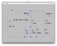
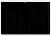
I slapped on a makeshift weird load to see what happens, with a coil in series with a resistor and also a cap, all that just added in parallel with the existing 4ohms resistive load.
I know this isn't the best fake load to approximate a speaker, but I can do that later. I just wanted to make it work and see how it looks.
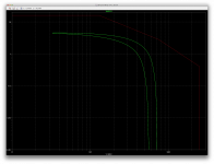
I only targeted Q11, which is only one of the outputs, but they should be identical and perhaps a little different at the negative side, yet similar enough.
The SOA curve comes from the datasheet that I have and it only has the 1sec curve. Maybe there are other datasheets with more curves, we can see about that later.
Anyway, if this is correct, even with that weird fake load, and only plotted within the 1sec soa curve, it looks well within the area.
Now I need to figure out why the perl script isn't working.
http://www.diyaudio.com/forums/solid-state/294790-using-ltspice-check-soa-violations.html
I made some adaptations to make it work for me on mac, but it didn't and I don't know yet why that is.
So I just went ahead with the hard way, manually!
I slapped on a makeshift weird load to see what happens, with a coil in series with a resistor and also a cap, all that just added in parallel with the existing 4ohms resistive load.
I know this isn't the best fake load to approximate a speaker, but I can do that later. I just wanted to make it work and see how it looks.
I only targeted Q11, which is only one of the outputs, but they should be identical and perhaps a little different at the negative side, yet similar enough.
The SOA curve comes from the datasheet that I have and it only has the 1sec curve. Maybe there are other datasheets with more curves, we can see about that later.
Anyway, if this is correct, even with that weird fake load, and only plotted within the 1sec soa curve, it looks well within the area.
Now I need to figure out why the perl script isn't working.
Attachments
Here, added the driver and annotations.
Better?
I need to get the perl script to work right. It's much more tedious work manually.
And btw, I made the fake load even harder.
Better?
I need to get the perl script to work right. It's much more tedious work manually.
And btw, I made the fake load even harder.
Attachments

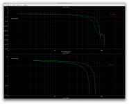
I tried coming up with some loads more similar to real ones. More complex.
I looked at an impedance curve over the audio range for a load made like 2 speakers, with xovers, for something that would be an 8ohms load.
The impedance curve looks pretty wild and the load doesn't drop below about 4ohms and change, but the reactive part really causes some phase shifting.
The interactions of those 2 fake speakers provide a very tough load I think.
I tried this out on our latest, and I'll post this next.
Is this load too hard?
Attachments
- Status
- Not open for further replies.
- Home
- Amplifiers
- Solid State
- grounded collector amp