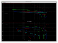
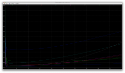
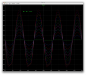
I only loaded it with that complex load, without the regular 4ohms resistive one.
At 20 and 1k it looks fine, but then at 10k and 20k we can see a slight encroachment out of the soa. Something to think about? Or is this load simply too hard?
At 20 and 1k it looks fine, but then at 10k and 20k we can see a slight encroachment out of the soa. Something to think about? Or is this load simply too hard?
Attachments
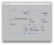
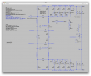
Testing an even more complex speaker load, 2way 8ohms nominal.
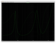
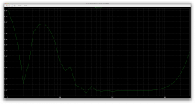
This is even wilder than the previous one, with the lowest impedance being around 1ohms in the 3-4khz range. Other than that, the impedance stays above 6ohms.
Both the impedance and phase shift curves are really wild, and the phase shift swings beyond +/- 60degrees.
I found an issue with this previous load, very likely the wild phase shift was causing the amp to run out of phase margin, so it caused a little oscillation, and that's what was causing the excursion outside the soa.
To fix this, a simple change of the global feedback cap from 33p to 27p, and all is well again.
I'll post the results with this different load next.
Attachments
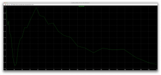
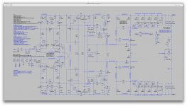
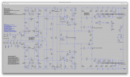
Here we are, with this 2way complex load.
The global feedback cap at 27p makes it work nicely and no oscillations can be detected, despite the large phase shift swings. And the sharp impedance droop at about 3.7khz needs to be looked at more closely, because it drops the impedance just a tad below 1ohms.
It seems that for normal complex 8ohms loads, this amp would probably have enough headroom in its soa with only 3 pairs.
When there were oscillations and I didn't know yet, I thought I'd test this with one more output pair, and the increase in soa wasn't enough in regards to the oscillations, which is no big deal, because we must avoid them, but I did see a nice improvement in thd though.
Adding one more pair may be enough to tackle a 4ohms complex load.
But with 5 pairs, that's more needed real estate on the heatsink for mounting.
It does run nicely with 5 pairs though, and lower thd.
Attachments

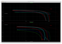
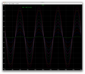
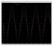
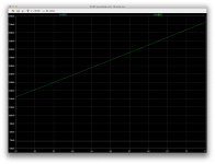
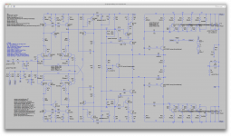
Here for comparison with our current 4 pairs, I simply added one more pair and tested only with the first complex load, as shown in the screenshots.
Having 5 pairs is a nice boost, that lowers thd nicely, except for the lowest frequency, and plenty of spare soa, even with that fake speaker load dropping impedance near 4ohms. So that's a somewhat typical 2way speaker load, 8ohms nominal.
With 5 pairs, it looks like it can handle a 4 ohms load fairly easily.
Attachments
-
 Screen Shot 2017-01-16 at 5.08.46 PM.png343.5 KB · Views: 95
 -
 Screen Shot 2017-01-16 at 5.08.41 PM.png87 KB · Views: 89
 -
 Screen Shot 2017-01-16 at 4.59.53 PM.png151.5 KB · Views: 101
 -
 Screen Shot 2017-01-16 at 4.59.29 PM.png355.9 KB · Views: 107
 -
 Screen Shot 2017-01-16 at 4.59.39 PM.png772.5 KB · Views: 109
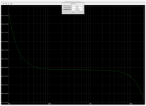
I think we need not beat ourselves over the head about the noise situation, because it really isn't bad at all after all.
The noise sim doesn't provide the full output signal like a transient sim does, so we can't calculate right there on the spot the actual SNR from the noise figure found.
Plus our numbers really aren't as bad as it looks, because we're not looking at the rms/integrated value on the plots. To get that value, we can have it with a measure statement, to use in some calculations, but since we can't get the output signal value, we don't get a real SNR from calculations, so the other way is to get it from the plot with the ctrl key, which gives us the integrated rms value, and that value does look a whole lot lower and better than what we see on the plot.
Then we can take that value and use the signal value from a transient sim to calculate manually the SNR.
Our noise plot, once integrated, gives us 32.351uV rms, so once we use the actual output signal, also rms, at about 39.453V, we can do the ratio and take the 20log of that, for a good result of nearly 122db.
Of course this is a simulation, with basically perfect supplies, as I only added series resistance to the low voltage one. So there is no extra noise or ripples from real supplies.
This could be simulated later, by adding stuff to make the ideal supplies seem more real.
Plus we can put together the low voltage supply with the regulators and rectifiers and whatever, to see what they can induce as ripples and noise.
I did some testing on simplified circuits to see what affects the noise most, and one large factor is the amp's gain itself, which in a way magnifies the noise from the input, and that's why we're seeing a seemingly high noise figure, but in reality it isn't that bad.
The resistor values also do a lot to noise, and we've seen that those acting on the amp's gain/feedback are the largest contributors. So the solution is definitely to lower their values as much as possible, but that's a difficult compromise, as there is a trade off somewhere else when lowering those values, especially on the input impedance.
As we can't have the centering resistors too low in value, we're kind of stuck where we are, and after the tweaks we've tried, some with a little success, I doubt we'd be able to bring the noise down much further anyway. It's pretty good as it is, and we can only hope the real supplies won't make that too much worse, as well as other things such as layout and parts properties.
The models aren't perfect, and some of them perhaps even suspect, so the sims may be somewhat close to real world but can also be off some.
Attachments
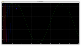
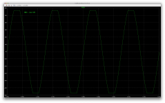
While doing more simulations, I bumped against something I had not seen before. Since we run transient sims ordinarily only in the audio range, I had not noticed this, but as I ran sims at lower than 20hz frequencies, this issue showed up. (see 1st attached shot)
I pushed the amp into clipping before, but in much earlier versions, and it wasn't exhibiting this behavior.
In this latest version, keeping the same input level as always, at 1.35V, it must be having a slight gain increase before rolling off at lower frequencies, so at 10hz, it goes very slightly into clipping, and we get that issue.
It doesn't look like oscillations, but more like a major case of sticking.
As I tried it at different frequencies, I found that it's doing fine all the way down to 13hz, and then does this at 12hz and below.
At first I thought maybe something is going on that's related to frequency, but quickly found out it actually does the same thing at any frequency if the input level is increased a tiny bit, to push it into clipping.
So it's not frequency related but rather clipping related.
Although we don't see signs of oscillations, it must be causing some tiny ones and it starts sticking and all the way to zero crossing.
Eventually I figured this was happening only at the vas and adding a couple of bav21 on it cured this issue.
I pushed it into much harder clipping and at all frequencies and this sticking issue is gone, with the added diodes.
I'll take a look again at thd at all frequencies to see what those diodes do.
Attachments


Good catch....
In this latest version, keeping the same input level as always, at 1.35V, it must be having a slight gain increase before rolling off at lower frequencies, so at 10hz, it goes very slightly into clipping, and we get that issue.
It doesn't look like oscillations, but more like a major case of sticking.
As I tried it at different frequencies, I found that it's doing fine all the way down to 13hz, and then does this at 12hz and below.
At first I thought maybe something is going on that's related to frequency, but quickly found out it actually does the same thing at any frequency if the input level is increased a tiny bit, to push it into clipping.
So it's not frequency related but rather clipping related.
...
Eventually I figured this was happening only at the vas and adding a couple of bav21 on it cured this issue.
I pushed it into much harder clipping and at all frequencies and this sticking issue is gone, with the added diodes.
I'll take a look again at thd at all frequencies to see what those diodes do.
Self cautions against this because it adds a non-linear capacitance to the first transistor's base. He believes it increases HF distortion in the VAS, because he identifies such nonlinear capacitances as major sources of HF distortion there.
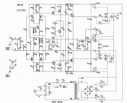
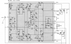
This is one reason we ground the collector of that first transistor, and operate the second transistor cascode. We evade Miller capacitance HF effects, and we evade non-linear capacitance effects simultaneously and at little cost. You may see this impact at higher frequencies. However, I've seen designers add this Baker clamp on the VAS several times, usually in second revisions of a production design, and for precisely this "stiction" reason. For instance, see the (circa 1980) Hafler DH 200 and DH 220 below.
In my judgement higher stability has priority over lower distortion, duh. We should endeavor to keep the diode capacitance small and the recovery time short, and Schottky's might be better, not sure. Looking forward to the sims.
Attachments
Self cautions against this because it adds a non-linear capacitance to the first transistor's base. He believes it increases HF distortion in the VAS, because he identifies such nonlinear capacitances as major sources of HF distortion there.
I've used this before in various sims. Sometimes with hardly any ill effect, and sometimes we just can't keep those diodes in there because they are quite harmful.
In this case, I ran a battery of sims to see how it affects thd at many frequencies, and so far I can say the diode's presence isn't being harmful and even hardly noticeable, even at hf.
I tried the bav21 first, as I mentioned, which cured the sticking issue, and then the bat54 (smt part only) which is supposed to have lower capacitance, and I looked at the possibility of using the 1N5819 that we've been using on the drivers, but that one has much higher capacitance, so no need to bother.
Finally after looking at more, I also tried the 1N5711, which would have the lowest capacitance of all of those.
Of course I can only try out the ones I have models for, and we have no certainty about the reliability of the models.
In our beloved guru cordell's models library, there are a couple of possible options, but only the bat85 would be an option and if I'm right, it would have a higher capacitance than the 1N5711, at least according to the model. Someone correct me if I'm wrong, but having looked at the models, it seems to me to be the CJO parameter that represents the capacitance, and in cordell's model of the bat85, it's at 7p.
My model for the bav21 has 270f for the CJO parameter, so I'm not sure what to make of it.
And as far as the 1N5711 model is concerned, the CJO is at 2p, which would be the maximum stated in the datasheet, so it appears consistent to me. The 1N5711 model would sport the lowest actual capacitance (model and datasheet).
Anyway, there is a bunch of data which is too much for a post here, so I'm just attaching the log files, with the diodes used identified in the file name. This can easily be compared side by side on screen.
I'd like to know more about this technically. How does this work.This is one reason we ground the collector of that first transistor, and operate the second transistor cascode. We evade Miller capacitance HF effects, and we evade non-linear capacitance effects simultaneously and at little cost.
For one thing, that diode is in parallel with the miller cap, and so we can always grab a rough average value or one more optimal, of the diode's capacitance, knowing it varies with frequency and mostly with reverse voltage, and then we can just subtract that from the miller cap value.
In this case it doesn't seem to be an issue, and I actually am more concerned about the much higher rise of thd at the low end, especially why there is a dip around 20hz and it rises above that, to go down again at higher frequencies.You may see this impact at higher frequencies.
It wouldn't be overly bad with the thd rise below 20hz, which isn't in the audible range, but 50-100 definitely is in the audible range, and that's where we have the highest thd overall.
I ran the sims up to 30hz, and even at 30khz our thd is lower than where we have the bump at the low end.
There must be an explanation for that thd rise at the low end and a fix for it, at least an improvement to make. Other than that, we've got pretty nice thd from 1k and all the way up to 30k.
Yes, I've seen this many times, even occasionally on an ltp, where I found that to be a big nuisance on every sim I tried.However, I've seen designers add this Baker clamp on the VAS several times, usually in second revisions of a production design, and for precisely this "stiction" reason. For instance, see the (circa 1980) Hafler DH 200 and DH 220 below.
I see in those mosfet haflers that they use diode based current sources. Those guys didn't use spice sims back then.
I just ran a big load of sims today on many variations of current souces, not the jfet based ones, just bjt, but with diodes, zeners, leds, cascodes, the works.
Too many to gather together, it gets messy, but I cut down on the numbers, by eliminating some.
I put a bunch of those current sources together in the same sim for comparisons.
I looked for their "stiffness" (output impedance), pssr and reaction on pulses.
I inspired myself from discussions around the forums and gathered what I could, to verify what they were saying, and I must admit, some were right about some things, and some were somewhat wrong.
I also found out that adding a cascode gives the best, by far, result for stiffness, but the extra complexity is there, and they are actually performing a little worse for pssr than simpler ones.
And although some swear by the diode types, or zener types, or even the led types, I found those to be the worst performers.
I'll try to clean up my results and post this here. It should provide some good insight, and some ideas for further sims could come out of it.
There may be fast switching types with low capacitance, like the bav21, that can do as well as the schottkys. For example the bav21 costs less than half the cost of a 1N5711 at mouser. Although the 1N5711 should have less than half the bav21's capacitance, the bav21 performed well in the sims.In my judgement higher stability has priority over lower distortion, duh. We should endeavor to keep the diode capacitance small and the recovery time short, and Schottky's might be better, not sure. Looking forward to the sims.
What needs to be investigated now is the cause for the higher thd at the low end. It's rather sizable, and we're above 0.1% at 10hz.
Attachments
Last edited:
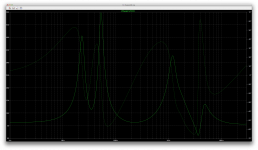
Here are some earlier results that I got after adding the bav21 diodes.
With the confirmation that the sticking is cured by forcing it into hard clipping.
I used the handy thd analyzer to gather thd sweeps over many frequencies. With many data points, the data amount gets really huge, and not only it grabs humongous amounts of disk space and takes a very long time to run, it also can crash ltspice. I had well over 30gb of data at some point, and the very long wait was in vain, when ltspice refused to work with the results, so after that I reduced the resolution to get a full spectrum curve, and then reduced the range with a high resolution again, to get a closer view on the low end where the thd rises.
We can see it starts rising sharply below 200hz, much more than it rises at the high end, and then curiously we get a big dip at 20hz. I wonder why...
What distortion mechanism is causing this heavier thd at the low end?
Attachments
-
 Screen Shot 2017-01-21 at 11.02.36 AM.png816.3 KB · Views: 84
 -
 Screen Shot 2017-01-21 at 11.02.22 AM.png351.8 KB · Views: 76
 -
 Screen Shot 2017-01-21 at 5.46.35 PM.png307.9 KB · Views: 95
 -
 Screen Shot 2017-01-21 at 5.42.54 PM.png269.9 KB · Views: 82
 -
 Screen Shot 2017-01-21 at 3.44.32 PM.png232 KB · Views: 98
 -
 Screen Shot 2017-01-21 at 3.45.26 PM.png791 KB · Views: 96
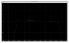
Looking a bit closer at our clipping behavior.
This is at 500hz, into clipping, and although it kind of looks clean, if we look closer, we can see it's not perfect, and there is even a little left over sticking with some ringing with tiny bit of overshooting.
Should we be concerned about this? Or as long as it's stable and not wreaking havoc, we can let it slide, because we should never let the amp clip anyway. (only on very short transients)
Attachments

This may be of interest, to more than just me.
I was curious about the output stages. How the gain works, what's determining it and how it's calculated.
If there would be oscillations, in the absence of a global feedback (there are none).
And really, how much actual gain those stages have?
I've been expecting an overall gain in the order of at least 4, maybe somewhere between 4 and 6 perhaps.
But I find it seems to be more like a little more than 40!!!
Is that really right?
Is there some component in the vas stage preceding this, being absent in this simulation, that contributes to determining the gain in the output stages?
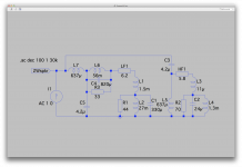
I just grabbed the whole output stages, the floating part only, everything after the vas, and since there is no vas to bias a bias spreader, I replace it with a simple voltage source.
To force the centering, I use an other voltage source applied to one side of the bias spreader, which doubles as the input for the signal to test it.
So I was able to recreate the operating point, and biased this about the same as the usual.
It's a little touchy to center it, and the bias affects the centering as well, so both have to be tweaked to bring it to proper centering and bias, but it's doable.
When I first applied a signal, I started at 10mV (peak sine 1khz). I haven't yet tried it at any other frequencies besides 1khz, it might be just as revealing.
Anyway, with a 1khz 10mV sine applied, it worked fine, and I had nearly 1.2V on the output (peak). That was the first surprise, with a gain a little over 40.
The thd was a little more than 0.8%, but the output signal looked rather fine, no crossover distortion visible or any real deformation.
I gradually increased the signal, all the way to 900mV, which brings it to the onset of clipping.
The clipping looks to be happening a little higher this way.
Would this mean we're clipping at the vas in this amp? So the vas would start clipping before the output stages. This wouldn't be bad really, as it should be a better and more behaved clipping.
The thd went up to above 7% at some signal levels, and went down to about 5.5% at that 900mV level. And we can see that although no noticeable crossover distortion seems to be there, there is a small visually noticeable distortion, as the since looks a little weird.
Should lower thd level be possible, or even expected on output stages?
We can see how much work the feedback has to bring this down to the rather nice result that we have globally. But if we could make the output stages more linear, this would improve the global result even more.
We may not even need that much bias current to prevent crossover distortion.
The output coil and zobel are still there, but besides that, the only compensation is done by the caps on the drivers.
Still, no oscillations occur, but non linearities are noticeable and obvious in the thd.
I'll run a stepped sim on the input signal level to have more details on the evolution of thd.
I was curious about the output stages. How the gain works, what's determining it and how it's calculated.
If there would be oscillations, in the absence of a global feedback (there are none).
And really, how much actual gain those stages have?
I've been expecting an overall gain in the order of at least 4, maybe somewhere between 4 and 6 perhaps.
But I find it seems to be more like a little more than 40!!!
Is that really right?
Is there some component in the vas stage preceding this, being absent in this simulation, that contributes to determining the gain in the output stages?
I just grabbed the whole output stages, the floating part only, everything after the vas, and since there is no vas to bias a bias spreader, I replace it with a simple voltage source.
To force the centering, I use an other voltage source applied to one side of the bias spreader, which doubles as the input for the signal to test it.
So I was able to recreate the operating point, and biased this about the same as the usual.
It's a little touchy to center it, and the bias affects the centering as well, so both have to be tweaked to bring it to proper centering and bias, but it's doable.
When I first applied a signal, I started at 10mV (peak sine 1khz). I haven't yet tried it at any other frequencies besides 1khz, it might be just as revealing.
Anyway, with a 1khz 10mV sine applied, it worked fine, and I had nearly 1.2V on the output (peak). That was the first surprise, with a gain a little over 40.
The thd was a little more than 0.8%, but the output signal looked rather fine, no crossover distortion visible or any real deformation.
I gradually increased the signal, all the way to 900mV, which brings it to the onset of clipping.
The clipping looks to be happening a little higher this way.
Would this mean we're clipping at the vas in this amp? So the vas would start clipping before the output stages. This wouldn't be bad really, as it should be a better and more behaved clipping.
The thd went up to above 7% at some signal levels, and went down to about 5.5% at that 900mV level. And we can see that although no noticeable crossover distortion seems to be there, there is a small visually noticeable distortion, as the since looks a little weird.
Should lower thd level be possible, or even expected on output stages?
We can see how much work the feedback has to bring this down to the rather nice result that we have globally. But if we could make the output stages more linear, this would improve the global result even more.
We may not even need that much bias current to prevent crossover distortion.
The output coil and zobel are still there, but besides that, the only compensation is done by the caps on the drivers.
Still, no oscillations occur, but non linearities are noticeable and obvious in the thd.
I'll run a stepped sim on the input signal level to have more details on the evolution of thd.
Attachments
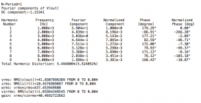
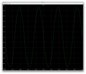
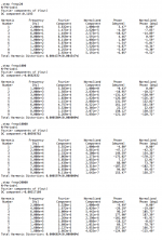
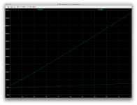
Here we are. Ran stepped sims at 20hz, 1k and 20k, and input at 10mV to 1V in 100mV steps.
Still no signs of any oscillation anywhere.
I posted the whole logs due to the amount of data. Makes it easier to view in a text editor and compare.
The one thing that is very odd is how the signal gets off centered a bit at 20hz, which makes the clipping happen earlier and on the negative side only.
Other than that, the clipping is rather smooth and not causing any issues. No overshooting, no ringing, no sticking, or oscillations...
I tried disabling the caps on the drivers earlier (at 1khz only), and didn't notice any difference.
Why do we have a gain over 40? and what really determines this?
Can this be made more linear? (cascoding?)
Attachments
-
OPS.log 20khz.txt10.8 KB · Views: 76
-
OPS.log 1khz.txt10.8 KB · Views: 76
-
OPS.log 20hz.txt10.7 KB · Views: 96
-
 Screen Shot 2017-01-26 at 12.31.02 PM.png606.7 KB · Views: 89
 -
 Screen Shot 2017-01-26 at 12.21.27 PM.png606.7 KB · Views: 106
 -
 Screen Shot 2017-01-26 at 12.24.36 PM.png585.2 KB · Views: 138
 -
 Screen Shot 2017-01-26 at 12.31.14 PM.png411.6 KB · Views: 282
I've been reading a bunch of stuff on the various topologies for output stages, along with the spice model parameters and the effects of temperature on the devices.
Although it's slightly altered, the output stage for this grounded source amp is made with sziklai pairs. The main difference, ignoring the base stoppers, is the outputs have their collector tied directly to the output, without going through a resistor, and the driver has a resistor going there.
Other than that small detail, it's a complementary compound pairs topo.
I ran some sims to see how the darlington type and the sziklai compare, when temperature is involved.
This is an important aspect, for proper thermal stability.
The darlington has an issue with thermal stability, which makes it much more difficult to keep under control. Plus it shows 2 x 2 junctions, for 4 junctions total to a bias spreader, and the thermal feedback to the bias spreader must be taken from the outputs, or a runaway is possible.
The sziklai on the other hand, only shows 2 junctions to the bias spreader, which makes is easier and simpler already, and most importantly, the drivers don't even need to be put on the main heatsink with the outputs, so the bias spreader sensor device can more easily be mounted with the drivers, as they are the only devices that really need to be sensed, and having such an arrangement with a separate and small sink makes it not only simpler and easier to assemble and conceive, it also provides a more speedy thermal feedback with less latency, for a bias control that's more rapid and precise.
This grounded source amp has quite a few advantages. It does have a few drawbacks, but not many and those are too major.
I've seen designers add this Baker clamp on the VAS several times, usually in second revisions of a production design, and for precisely this "stiction" reason. For instance, see the (circa 1980) Hafler DH 200 and DH 220 below.
I don't see baker clamps on the 200, only on the 220. I suppose it didn't have them earlier and they added them later for that reason.
I see they made use of diode based current sources, and they even used several diodes. This isn't the best performing source and they're not so good on noise.
Having run a bunch of comparison sims, I prefer the simple dual transistor one, for simplicity compared to good performance. We can improve, often by making some trade offs along the way, but as we improve, the part count grows fast.
I've seen a couple of other topos I haven't tried in the comparisons, and those seem intriguing. Plus I've seen mcintosh using the same dual transistor sources, with no base stoppers, but with a small cap between the transistor bases. I wonder why. Tests suggested those are more harmful than beneficial.
I've been trying to simulate the thermal aspect of this amp for a while now.
I haven't done much thermal sim before, so I'm not too sure exactly what would be best to look at.
Thinking that perhaps the output stage could be viewed as a compound pair based topo, although it's grounded collector, the bias spreader might be best at tracking the drivers temp and not so much the outputs.
But the sims don't seem to agree that much.
I tried various ways, grouping the outputs as being on a main sink with the same temp amongst them, and possibly a separate sink for the drivers, and then the bias spreader sensor could be attached to either of them, or everything could also be viewed as being on one single sink.
The drivers don't dissipate that much on their own, and if they were on their own sink, it probably wouldn't get too warm.
In the results posted here, I put everything together on the same main sink, but added a slight temp differential between parts to account for the losses.
The drivers not generating so much heat, would be actually heated much more by the outputs than their own heat.
I arbitrarily put 2 degrees of difference between the outputs and the drivers, although I suspect it might even be higher when the amp is putting out a lot of power, where the heat would take a bit of time to be transmitted to the drivers.
And then the bias spreader doesn't put out any heat, so all of it comes from the main sink. I put 4 degrees of difference, but if it tracks well, maybe it's less than that.
A good thing to do, assuming the drivers are the main ones to track, would be to slap the bias spreader sensor right on top of a driver, but those are TO220 and that may not be so easy for good thermal contact.
When the temp is kept the same for the sensor and the drivers, the bias in the drivers stays very constant, but the output's does climb, so they should also be sensed, but this simulation shows that with all of them on the same sink, the drivers bias remains nicely constant, while the output's does climb.
This would indicate the bias spreader sensor doesn't correct enough to keep the output's bias sufficiently constant.
I need some input about this. Either I'm looking at this wrongly, or something needs to be done to the bias spreader to make it track better.
Attachments

Here is an other way to look at this thermal situation:
Assuming a separate sink for the drivers, and the bias spreader sensor on that sink. I put a warm and fixed temperature on that sink to see what happens with the main sink when its temperature varies.
And the result is basically the same as previously, with everything tracking together.
The output's bias does increase, and by about the same amount. So keeping the same temp on drivers and outputs doesn't really change things that much.
The drivers' bias is rather constant as well, so the bias spreader sensor does keep that part of it well controlled, although a small amount of drift can be seen for that driver bias, going slightly down, but it's tiny.
Attachments
One more experiment to see how the bias spreader sensor is effective at temp tracking:
I kept the bias spreader sensor at "normal" temp, steady and not stepped.
Then the drivers and outputs on the same sink, with just a couple of degrees differential for the drivers.
It shows that if the sensor isn't tracking, the bias climbs a whole lot more, especially in the outputs, and of course a runaway would be likely.
The rise isn't so significant in the drivers, but that small rise has to contribute to the sharp one in the outputs.
Perhaps it's not too important in the drivers, but the outputs temp must obviously be tracked. So the assumption about the sziklai config doesn't hold here.
The MJL outputs being plastic cases, it would be fairly easy to mount the bias spreader sensor right on top of one of them, for tighter tracking.
Attachments

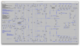
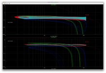
In the quest for a more controlled tempco for the bias spreader, I tried a few variations and here is one that works much better. Although not perfect, I wonder if this can be considered "sufficient", as the bias current remains below 150mA when the sink is quite hot.
This sim was without a temp difference between the sensor and the sink, so in reality, with the difference and lag, this would be a little worse.
This is assuming all devices are on the same sink, and the extra diode in the spreader remains at ambient, which senses that temp to further control bias.
As the curves show, the ambient temp plays its role via that diode.
Perhaps there may be a way to increase further the correction, with 2 diodes instead of one...
One thing is for sure, the best control is done with all parts together on the same sink.
Attachments

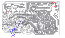
I've been looking at various QSC builds, to see how they handle the thermal coupling for the bias sensors.
They are the specialist of the grounded collector concept, as nearly all their amps are built that way.
I suspect the thermal stability doesn't seem to be overly difficult, as looking at the usa400 as an example, which is very similar to other models like the qsc1200 and qsc1400.
For one thing, they do not bother putting all the devices on a single sink, and the main sink for the outputs is as we expect it, rather "slim". Plus each driver is only on its own small sink, very basic.
They don't use transistors for the bias spreaders, as they have opamps driving this and they only use diodes with an NTC.
As I see it, they track only roughly the outputs with the diodes, and not the NTC. The diodes are placed on the pcb to be in contact with the main sink, but barely, with no attempt at making a solid thermal bond, just shove the diodes against it as is.
The NTC isn't even in contact with anything, as it's just positioned very near but not in contact with the driver's sinks.
So the drivers temp is barely tracked, only really by the proximity of the NTC, and they're not being cooled a lot.
The real tracking, done by the diodes near the main sink, isn't made to be very efficient, with only a close proximity and nothing done to make really good contact.
From the sims, I can see the drivers bias current doesn't vary very much. It remains rather stable, so no big need to track them.
However the tiny drift on the drivers does get amplified on the outputs, with a much larger drift, but it doesn't look like it would go into a runaway, even with a rough thermal tracking as what's done with the diodes.
As I understand it, 2 junctions are acting to make the bias drift, the drivers, and thus 2 diodes provide 2 junctions as well to compensate, but the temperature being tracked isn't from the drifting junctions but rather the outputs.
They do have a separate PTC on the main sink, tracking temp, but not for the bias control, as it's used for the thermal shutdown.
Looking at their flimsy main heatsink, and what they put on the drivers, those amps really don't have much trouble being cooled, and the sinks are small.
Attachments
To be honest, I've never understood this statement on the Sziklai's....but the outputs temp must obviously be tracked. So the assumption about the sziklai config doesn't hold here.
One thing is for sure, the best control is done with all parts together on the same sink.
Same thoughts here.
Looking at their flimsy main heatsink, and what they put on the drivers, those amps really don't have much trouble being cooled, and the sinks are small.
Do they possibly use forced convection by a fan?
Best regards!
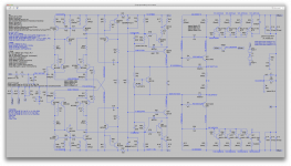
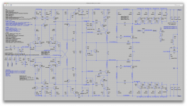
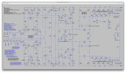
Addendum: Perhaps you might want to read the threads on Behringer power amps elsewhere in this board, e.g. this one: http://www.diyaudio.com/forums/instruments-amps/267828-behringer-bx3000t-bass-head.html
Here's the schematics: diyAudio
Last edited:
- Status
- Not open for further replies.
- Home
- Amplifiers
- Solid State
- grounded collector amp