I have never used a professional microphone, dynamic, ribbon or condenser that was not balanced. What advantage would balanced give them that it would no give to a phono cart? Or is it just the cable length difference?
Anyhow, it would be nice to see some different approaches covered. Balanced, DSP, passive vs active or split and so on.
The transducer in a condenser mic is not balanced, and if you have a low output impedance buffer in the mic it works fine unbalanced at the same cable lengths as an ordinary phono connection. Mics typically are expected to work in far harsher environments than playing LP's in a livingroom.
I have never used a professional microphone, dynamic, ribbon or condenser that was not balanced. What advantage would balanced give them that it would no give to a phono cart? Or is it just the cable length difference?
Anyhow, it would be nice to see some different approaches covered. Balanced, DSP, passive vs active or split and so on.
I think those are balanced preamps, does not mean the diaphragm at the input side is connected balanced.
I looked at a few miles recently, and they were not balanced at the input, but did drive the cable leaving the mike balanced.
Jan
Hello,
Some years ago, I built this phono preamplifier with differential inputs.
Instead of center tap load (2*23.5k), I used 47k plus 1meg from each terminal to ground.
If I make it single ended by connecting one end to ground and put the 2 *1meg one the other end, The noise will be exactly the same.
Some years ago, I built this phono preamplifier with differential inputs.
Instead of center tap load (2*23.5k), I used 47k plus 1meg from each terminal to ground.
If I make it single ended by connecting one end to ground and put the 2 *1meg one the other end, The noise will be exactly the same.
An externally hosted image should be here but it was not working when we last tested it.
Hello,
Some years ago, I built this phono preamplifier with differential inputs.
Instead of center tap load (2*23.5k), I used 47k plus 1meg from each terminal to ground.
If I make it single ended by connecting one end to ground and put the 2 *1meg one the other end, The noise will be exactly the same.
An externally hosted image should be here but it was not working when we last tested it.
This is always true of the voltage noise in all the circuits, there is just some confusion here. 2 - 23.5k resistors and 1 - 47k resistor have the same noise.
Sure, statistically the noise is the same, but who/what says it's perfectly white.This is always true of the voltage noise in all the circuits, there is just some confusion here. 2 - 23.5k resistors and 1 - 47k resistor have the same noise.
What happens when different resistor types of these two values are combined, there ought to be a conjugate difference.
Dan.
Maybe a guide for making step-up transformers? A friend made his own small toroid from bigger toroid material and wound it 11-filar for stepup. And now I found some nice 24 V (10:1) toroid adapters (wall warts) . What can we use?
Sure, statistically the noise is the same, but who/what says it's perfectly white.
Without DC current physics says it is unless there some chemical pathology driving it.
> doubling up an expensive RIAA network is inelegant
No need to double-up. You may hate the answer. Attached.
100Meg dummy resistors just placeholders.
The inductances and corner freqs are dart-boarded to a right octave but will need better calcs for accuracy.
The size of C23 is embarrassing, true. There are other ways.
First consider without R77. If cart is truly floating, or balanced, output is balanced. If one side of cart gets grounded, output is poorly "balanced".
Now connect R77. The lower output is a true SE of the differential input.
I must say that ignoring poor contacts in plugs and green-lead, essentially all the hum in dozens of systems was stray field from motors, PTs, lamps and such getting into the cartridge. First clue is that the hum changes as you move the arm. I have had to compromise for lowest field on the record, allowing some small hum on the arm-rest. I have had to tell users they could NOT put that reading lamp right next to the turntable (or if they did, don't complain to me). I have not observed any hum I thought was common-mode.
Attachments

This is always true of the voltage noise in all the circuits, there is just some confusion here. 2 - 23.5k resistors and 1 - 47k resistor have the same noise.
It's ~what I wanted to saiy.
I now use this one, current mode that does not seem to be much used and that could possibly have a few lines in a new book. The idea is to have a low impedance connection between the cartridge and the preamp for better protection against pertubations.
![IMGHTTPDEAD]](/community/proxy.php?image=http%3A%2F%2F%5BIMGHTTPDEAD%5Dhttp%3A%2F%2Fherve00fr.pagesperso-orange.fr%2FFiles%2F190_v15_5_courant_01.png%5B%2FIMGHTTPDEAD%5D&hash=8b2188f73c03799872e7c29bf0e903c0)
LOL. OK thanks guys. Yes I know that condenser mic elements are not balanced, but someone goes to great pains to make the output so. And a ribbon mic has a transformer.
Think dynamic mic = MM and ribbon = MC.
Given that the source is floating you see no advantage to the balanced connection over the few meters wire typical to phono wiring? No CMRR advantage?
Think dynamic mic = MM and ribbon = MC.
Given that the source is floating you see no advantage to the balanced connection over the few meters wire typical to phono wiring? No CMRR advantage?
Pano wrote: I have never used a professional microphone, dynamic, ribbon or condenser that was not balanced. What advantage would balanced give them that it would no[t] give to a phono cart?
Scott wrote: Mics typically are expected to work in far harsher environments than playing LP's in a livingroom.
Exactly.
The benefit of using a floating cart with shielded twisted pair cable into an instrumentation amp realizing common mode rejection is...
...Less induced hum in the transmission line from cart to preamp.
The same reason it is universally used in microphone, line and telephone circuits.
The balanced input preamp I designed is for professionals in far harsher environments than your typical living room. Cutting lathe, stage, DJ booth etc...
Residential wood stud homes do not have structural elements which radiate magnetic hum fields. (They do however have magnetically-ballasted lighting.) Commercial buildings do have structural members that radiate - with building steel sometimes carrying amps of current. That current can, and often does, radiate into signal leads.
A cutting lathe also provides a harsh electrical environment. What clients were asking for was essentially a remotely-located, relatively small "active transformer" that could be used to buffer the cartridge lines from the lathe-mounted playback arm to the transfer console monitor input. Galvanic isolation from the lathe frame is possible.
Splitting the RIAA onto a separate board was done primarily for transfer applications and monitoring flexibility.
I don't recommend the THAT mic preamps (or INA217/SSM2019) for either MM or MC preamps. They are optimized for mic source impedances. The current noise is too high for MM and the internal front end transistor base resistance too high for MC. You can make an OK MC preamp using a THAT1512 or 1570 et al. The THAT300-series also have base resistances more suited for mic preamp applications. When paralleled they still cannot match a single pair of ZTX851/951.
The model shown earlier for a balanced RIAA preamp will have poor CMRR owing to common mode rejection being realized downstream from the dual RIAA networks. A fully-differential RIAA would solve that problem but realizing CMRR ahead of EQ seems more efficient.
As to de-clicking flat or post-EQ I'm still not sure which sounds better but I can say that setting thresholds is far less critical in the flat domain.
I do not like the sound of FIR RIAA EQ. I prefer the analog. I've just gotten some IIR RIAA EQ vst plug-ins to try but I haven't spent enough time comparing them.
I have clients that use the flat preamp with JRiver and other streaming apps and they seem to be happy with it.
EDIT: Just found a comparison between RCA/Coaxial and Floating/STP: http://www.proaudiodesignforum.com/forum/php/viewtopic.php?f=6&t=423&start=134
These tests were done with an S681 mounted on an arm.
Unbalanced RCA connections with a grounded differential input:
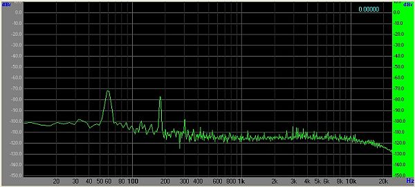
Balanced Flat Phono Preamp with RIAA EQ Applied, Noise Floor, Unbalanced coaxial RCA Connections, Grounded Differential Input, Stanton 681
Balanced shielded twisted pair connections with a fully differential input:
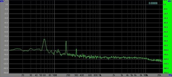
Balanced Flat Phono Preamp with RIAA EQ Applied, Noise Floor, Balanced Shielded Twisted Pair Connections, Fully Differential Input, Stanton 681
The difference in "hash" between 1-10 kHz is significant.
The 60 Hz hum is about 6 dB less.
Last edited:
Exactly.
I don't recommend the THAT mic preamps (or INA217/SSM2019) for either MM or MC preamps. They are optimized for mic source impedances. The current noise is too high for MM and the internal front end transistor base resistance too high for MC. You can make an OK MC preamp using a THAT1512 or 1570 et al. The THAT300-series also have base resistances more suited for mic preamp applications. When paralleled they still cannot match a single pair of ZTX851/951.
As to de-clicking flat or post-EQ I'm still not sure which sounds better but I can say that setting thresholds is far less critical in the flat domain.
I do not like the sound of FIR RIAA EQ. I prefer the analog. I've just gotten some IIR RIAA EQ vst plug-ins to try but I haven't spent enough time comparing them.
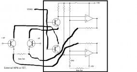
I got distracted and didn't post my circuit. The new THAT pre-amps bring out enough pins to allow substitution of the input pair with external JFET's or NPN's with a large latitude for setting bias level. The ZTX devices would probably need an offset servo. I think any cart could be optimally noise matched. Excuse the crude drawing, the input pair is pulled up to a bias voltage and becomes the cascode for the external devices seems a win-win. I have built this with other in-amps but I need to fill in the details here after I get some samples.
Most of my references also agree on flat de-clicking.
You can do minimum phase FIR RIAA with nearly perfect results all tools that I have seen do linear phase FIR which distorts the envelope of any complex signal. I could post a demo the min-phase actually has fewer coefficients, and can be done with no windowing i.e. zero low frequency ripple.
Attachments
Last edited:
The ZTX devices would probably need an offset servo.
They definitely do need a servo.
They definitely do need a servo.
What collector current do you like on the ZTX devices? Over a certain amount some extra attention to preserving headroom is needed in that circuit.
I have to give credit to John Roberts who published his "P10" preamp in Popular Electronics March 1981.
Page 71: http://americanradiohistory.com/Archive-Poptronics/80s/1981/Poptronics-1981-03.pdf

Roberts P10 Phono Preamp Popular Electronics March 1981.
About the time John published his article Logitek patented a balanced input phono preamp. Infringement avoidance explains the RCA connection at the input.
Page 71: http://americanradiohistory.com/Archive-Poptronics/80s/1981/Poptronics-1981-03.pdf
Roberts P10 Phono Preamp Popular Electronics March 1981.
About the time John published his article Logitek patented a balanced input phono preamp. Infringement avoidance explains the RCA connection at the input.
Hello,
Some years ago, I built this phono preamplifier with differential inputs.
Instead of center tap load (2*23.5k), I used 47k plus 1meg from each terminal to ground.
If I make it single ended by connecting one end to ground and put the 2 *1meg one the other end, The noise will be exactly the same.
An externally hosted image should be here but it was not working when we last tested it.
Have a look, page 79 (just as the EF Taylor's circuit, I know this one since its date of publication) :
http://www.americanradiohistory.com/Archive-Poptronics/80s/1981/Poptronics-1981-03.pdf
Recent versions :
Pro Audio Design Forum • View topic - Flat Phono Preamp Based on John's P10 and 2SK389
What collector current do you like on the ZTX devices? Over a certain amount some extra attention to preserving headroom is needed in that circuit.
I used far more collector current than necessary (7.5 mA) just to see how low a NF I could get and yes there was a resulting loss of headroom. Pro Audio Design Forum • View topic - A Low Noise Balanced In Moving Coil Preamp Using the ZTX851
The circuit thus far is a simple proof-of-concept to see what the ZTX851 are capable of. It should do quite well with a far lower Ic.
Have a look, page 79 (just as the EF Taylor's circuit, I know this one since its date of publication) :
http://www.americanradiohistory.com/...cs-1981-03.pdf
Recent versions :
Pro Audio Design Forum • View topic - Flat Phono Preamp Based on John's P10 and 2SK389
Which leads us back to here circa 2015: Pro Audio Design Forum • View topic - Phono Transfer System

A Flat Balanced Input/Balanced Output Moving Magnet Phono Preamp
Douglas takes issue with bias current flowing through the cartridge.

Where is the reactance of your "mandatory" input coupling capacitors modeled? (Two are required.) They appear in series with the source impedance - raising it at LF - and increase LF noise voltage from op amp current noise flowing into the source.
The model - and preamp - is probably better off without them.
Last edited:
I have to give credit to John Roberts who published his "P10" preamp in Popular Electronics March 1981.
Page 71: http://americanradiohistory.com/Archive-Poptronics/80s/1981/Poptronics-1981-03.pdf
Roberts P10 Phono Preamp Popular Electronics March 1981.
About the time John published his article Logitek patented a balanced input phono preamp. Infringement avoidance explains the RCA connection at the input.
The circuit was published as a data amplifier in 1968 so the basic architecture was prior art and the patent would have to be weak.
Last edited:
- Home
- Source & Line
- Analogue Source
- What would you want to see in a book on electronics for vinyl replay? Douglas Self.