Yes that appears to be the grand daddy of them all. I think John Roberts was inspired by the work of Paul Buff of Valley People who in turn followed in time at least the work of Demrow. I've never seen anything like Demrow that predates it and give him and you credit in Ballou's "Handbook for Sound Engineers."
I would link to the Demrow paper but my site is down.
Very weak indeed. And not hard for the constructor to circumvent.
Les Tyler and I wrote: Current feedback amplifiers have a history rooted in instrumentation amplifiers. The challenges of amplifying low-level instrumentation signals are very similar to microphones. The current feedback instrumentation amplifier topology, known at least since Demrow’s 1968 paper, 26 was integrated as early as 1982 as the Analog Devices AD524 developed by Scott Wurcer. 27 A simplified diagram of the AD524 is shown in Fig. 12- 55. Although the AD524 was not designed as an audio preamp, the topology it used later became a de facto standard for IC microphone preamps. Demrow and Wurcer both used a bias scheme and fully balanced topology in which they wrapped op-amps around each of the two input transistors to provide both ac and dc feedback. Gain is set by a single resistor connected between the emitters (shown as 40 Ω, 404 Ω, and 4.44 kΩ) and feedback is provided by two resistors (R 56 and R 57 ). The input stage is fully symmetrical and followed by a precision differential amplifier to convert the balanced output to single-ended. Wurcer’s AD524 required laser-trimmed thin film resistors with matching to 0.01% for an 80 dB common-mode rejection ratio at unity gain.
Audio manufacturers, using variations on current feedback and the Demrow/Wurcer instrumentation amp, produced microphone preamps based on discrete low-noise transistor front-ends as early as 1978; an example is the Harrison PC1041 module. 28 In December of 1984, Graeme Cohen also published his discrete transistor topology; it was remarkably similar to the work of Demrow, Wurcer and the Harrison preamps. 29
I would link to the Demrow paper but my site is down.
The circuit was published as a data amplifier in 1968 so the basic architecture was prior art and the patent would have to be weak.
Very weak indeed. And not hard for the constructor to circumvent.
Last edited:
I would link to the Demrow paper but my site is down.
Bob has passed away, but my first design manager knew him and said that the idea was in use in moving coil geophones. I tried years ago to find an old service manual or anything but came up empty handed.
Demrow, Robert, "Evolution from Operational Amplifier to Data Amplifier," Analog Devices, September, 1968.
http://www.waynekirkwood.com/images/pdf/ADI_Demrow_Evolution_from_Op_Amp_to_Data_Amp.pdf
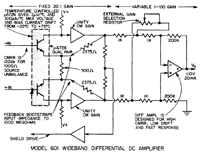
Analog Devices Model 601 Instrumentation Amp, Demrow, 1968

Analog Devices AD524 Instrumentation Amp, Wurcer.
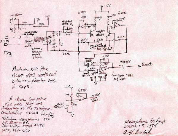
Benchmark Mic Preamp drawn by it's designer, Al Burdick, 1984.
US4293823 Balanced Input Phonograph Preamplifier, 1981: http://www.waynekirkwood.com/images/pdf/US4293823_Balanced_Input_Phonograph_Preamplifier.pdf
http://www.waynekirkwood.com/images/pdf/ADI_Demrow_Evolution_from_Op_Amp_to_Data_Amp.pdf
Analog Devices Model 601 Instrumentation Amp, Demrow, 1968
Analog Devices AD524 Instrumentation Amp, Wurcer.
Benchmark Mic Preamp drawn by it's designer, Al Burdick, 1984.
US4293823 Balanced Input Phonograph Preamplifier, 1981: http://www.waynekirkwood.com/images/pdf/US4293823_Balanced_Input_Phonograph_Preamplifier.pdf
Last edited:
Demrow, Robert, "Evolution from Operational Amplifier to Data Amplifier," Analog Devices, September, 1968.
One clarification, IIRC Bob was an applications engineer and the 601 was in reality designed by John Cadogan. I met his son, John also, at Teradyne while doing the AD797. Leaving names out, I was looking for a first big project and the AD524 was first proposed as a "gothic" three op-amps on a chip disaster. My boss described it as "sabotage", the lead designer left, we scrapped everything and my boss said here John Cadogan did this go with it. There was no simulation at the time, everything was breadboarded with discretes that our fab made up.
🙂🙂🙂The new THAT pre-amps bring out enough pins to allow substitution of the input pair with external JFET's or NPN's with a large latitude for setting bias level.
You can do minimum phase FIR RIAA with nearly perfect results all tools that I have seen do linear phase FIR which distorts the envelope of any complex signal. I could post a demo the min-phase actually has fewer coefficients, and can be done with no windowing i.e. zero low frequency ripple.

Guru Wurcer, I may have asked you for this before.
Is there an electronic copy of how to do this that might be available to Ozzie beach bums?
My naive attempts at EVIL FIRs with no ripple haven't been much good, the best being a crude Remez Exchange. Usually the ripples appear gain if you look at the response with a bigger FFT block. They are hidden in the crevices between the FFT frequency bins.
IIRs are of course Digital Filters as God intended. 😀
One definition of Minimum Phase is of course the shortest possible impulse that can meet a frequency response spec.
🙂🙂🙂
Guru Wurcer, I may have asked you for this before.
Is there an electronic copy of how to do this that might be available to Ozzie beach bums?
Sure I'll package it up, ironic that this analog guy could hack this. It is in my LA article left as an exercise for the reader.
Last edited:
I would say to Douglas make the book as fat as possible. I would like to see bare facts on for example common base MC stages. Base spreading resistance for devices we can easilly buy. Perhaps BD139/140, BC327/337 etc. Quad MC input of old. It's a nice idea with some problems.
I would like to be able to dial up any EQ I want without too much maths ( Rod Elliot did a good job, Project 91 ). Picky ideas about phono stages are minor compared with wrong EQ. Many LP's need EQ.
I would use Denon DL 103/110 and Shure M44-7 as reference PU's. None are of these are easy to suit. Ideally gain settings between these would be useful.
Looking at a NAD 3020 I repaired yesterday ( C407/8 in phono ) 4u7 is used in the MM input. Seems a 10 uF film cap could be tried. I don't find DC through the PU a problem. Could be JFET's could suit better. Maybe banked up JFET op amps would work OK for noise. I have only tried this with bipolar types and had rather good results.
One idea would be to switch off the inputs of a NE5534 and use an external LTP into the comp pins. This could yeild very low noise for pennies.
I would also like to see an all passive design that attempts to work better than an active design. I am not interested that it really is. Just it has worked through data.
Also I would like to see a really minimal design that is not just an op amp. Perhaps the Quad input pair with passive 75 uS and active 3180/318 ( + 2 uS passive ? ) .
Happy Christmas Douglas and all. It was New Year yesterday, strange no one says it! I am late for a bus in Oxford so please correct any English.
I would also like to see an all passive design that attempts to work better than an active design. I am not interested that it really is. Just it has worked through data.
Hi everyone and a Happy New Year
Nigel, I'm currently working on just that. Not because I believe it to be better, but I've read so much about it I decided to have a go at it.
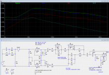
It's a bit of a challenge to nail it - the eternal battle between noise and headroom. I've attached my design, so feel free to have a go at it.
Currently I'm in the build phase, so I cant tell you how it sounds. Only this : the first OPA *must* be a FET-input (due to bias etc.)
Attachments
Noise
Let me start by saying that I would welcome a comprehensive book on the subject from D. Self!
I have a few questions about noise that I believe should be answered:
- How much noise (from the amplifier) is OK?
- When does the fight become futile ? ie when are you just claiming the bragging right ?
- How do you fight it ? (noise that is)
- What kind of noise are we talking about anyway ?
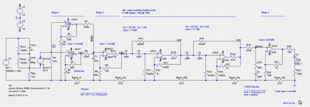
I'm currently working on a (relatively) simple amplifier with a differential and active input - see attachments.
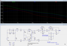
I know You are not too convinced about the joy of differential RIAA amps, but if you take a look at the noise curves, it is quite obvious, that the "4OPA all diff" has a *much* higher noise level below 10 Hz than the "4OPA all diff w HP" mainly due to the fact, that the input resistors (R9 & R10) is in parallel with the cartridge at all times.
If the input resistor(s) is allowed to be "detached" for VLF you will have all the noise from the much larger (47k) input resistor. Further, a differential input is just a special case of parralled amplifiers, ie the noise from both input resistors and OPAs are reduced with 3dB. Another advantage of a differential input is that you can use BJT based OPAs *without* input capacitors, as long as they are matched (LM4562 ?)
I may be wrong, but I think that excessive sub-sonic noise may put a veil over the lower bass, so everything sub-sonic has to go, hence the third order filter.
The bottom line is - I guess - that differential amplifers has something to offer in terms of reducing noise while preserving a large headroom, and that I would love if you would dedicate a section to the subject.
Let me start by saying that I would welcome a comprehensive book on the subject from D. Self!
I have a few questions about noise that I believe should be answered:
- How much noise (from the amplifier) is OK?
- When does the fight become futile ? ie when are you just claiming the bragging right ?
- How do you fight it ? (noise that is)
- What kind of noise are we talking about anyway ?
I'm currently working on a (relatively) simple amplifier with a differential and active input - see attachments.
I know You are not too convinced about the joy of differential RIAA amps, but if you take a look at the noise curves, it is quite obvious, that the "4OPA all diff" has a *much* higher noise level below 10 Hz than the "4OPA all diff w HP" mainly due to the fact, that the input resistors (R9 & R10) is in parallel with the cartridge at all times.
If the input resistor(s) is allowed to be "detached" for VLF you will have all the noise from the much larger (47k) input resistor. Further, a differential input is just a special case of parralled amplifiers, ie the noise from both input resistors and OPAs are reduced with 3dB. Another advantage of a differential input is that you can use BJT based OPAs *without* input capacitors, as long as they are matched (LM4562 ?)
I may be wrong, but I think that excessive sub-sonic noise may put a veil over the lower bass, so everything sub-sonic has to go, hence the third order filter.
The bottom line is - I guess - that differential amplifers has something to offer in terms of reducing noise while preserving a large headroom, and that I would love if you would dedicate a section to the subject.
Attachments
This all looks to be a book I would enjoy. Question with answers as Douglas's books often are. Douglas always makes it clear what he prefers. At least he steps back enough for us to enjoy what he shares.
I think I would like a headphone phase correction circuit if Douglas thought it worth a few pages. Maybe a version of the NE5532 power amp. I tried this myself and got nowhere. The recent debate about Vinyl verses CD makes me think this would not be a waste of paper. Could it be what Vinyl has as errors might be how we like things. All we need is a recipe to play with. I don't much like heaphones. I suspect it is just the false stereo image I hate and LP scratches in the centre of my head. A very basic preamp also could be part of the headphone amp with ideas on switches. It would drive any cable if so. I would say 4Vrms would be useful as a universal device. Just a thought.
I think I would like a headphone phase correction circuit if Douglas thought it worth a few pages. Maybe a version of the NE5532 power amp. I tried this myself and got nowhere. The recent debate about Vinyl verses CD makes me think this would not be a waste of paper. Could it be what Vinyl has as errors might be how we like things. All we need is a recipe to play with. I don't much like heaphones. I suspect it is just the false stereo image I hate and LP scratches in the centre of my head. A very basic preamp also could be part of the headphone amp with ideas on switches. It would drive any cable if so. I would say 4Vrms would be useful as a universal device. Just a thought.
My own investigations into noise were different to how I thought it would sound. I banked up some MC33079 ( what I had mostly , dead bug ) . Thus what had been 1+1 became 3+1 in an RIAA circuit where the 75 uS was a passive circuit ( the 3 ) followed by an active 3180/318 gain 17 at 1 kHz. The gain of the first stage 62. The big surprise was detail at least as good as before and a warmer sound ( valve like is my best way of saying it ) . The latter is logical from how noise works as numbers. It was the only time in my life that a more complicated circuit sounded as if a curtain had been removed. Most of you will know why and even doubt I should have said this. Others will think it close to magic if they try it. I did pass the current through the Lyra Helikon. From memory 10 mV at 47K = < 1/4 uA. I could be wrong so forgive. The Lyra needs only that, this suits other uses. As the coil 5R and PU wires 2R the meter gives no readable voltage offset when loaded down. Even so various resistors still change the sound. Stangely carbon comp is not the worse on measurments due to the shunt of the PU. I can only assume the problems are a 100 kHz when inductance takes over. Foil types were best. If asking, like the stylus was super clean. Ironic as some of my records should never see the Lyra. Even they seem newer. I had the chance to compare the LT1115. It was lower in noise and yet not really better. I am told it can be more easilly upset so suspect it was that.
http://cds.linear.com/docs/en/datasheet/lt1115fa.pdf
http://cds.linear.com/docs/en/datasheet/lt1115fa.pdf
I would like to thank everyone participating for their suggestions as to the new book.
Most of them I accept, with these provisos:
No mechanical stuff. It is not my speciality, and it's not the sort of thing that most of us can experiment with at home. Also, the provisional plan shows that the book will be a hefty volume. Making it much bigger is not practical publishing. If someone wants to write "Mechanics for Vinyl" I will be glad to see it.
Not much on balanced phono inputs. We have had much discussion, and I still see little or nothing to be gained by the extra complication.
Not much on passive RIAA eq. However you shake it or bake it, it's a bad idea. Come on now, apply yourself to the Lipshitz equations and do it properly. Active, in one stage.
Why genuflect towards "The Lipshitz Equations" as though they are some kind of wondrous revelation? It's just plug-and-grind circuit analysis in the Laplace domain. Detail oriented, boring, full of opportunities for minor errors, but not the least bit innovative. It's a perfect assignment for a posse of graduate students (in the 1970s). Today you can hand it off to a symbolic algebra computer system like Maple and get The Right Answer immediately. The only "value add" from Prof. Lipschitz is that he and his grad students slogged through the algebra and checked it and double checked it (and forced the JAES reviewers to double-double check it), so that you don't have to. Now that you have Maple software, you don't need Lipschitz and you also don't need a gallon of coffee and two pads of notepaper.
I see you object to measured data on real life vinyl playing systems which do not confirm your prejudices.Not much on balanced phono inputs. We have had much discussion, and I still see little or nothing to be gained by the extra complication.
If the idea of the new book is to present new and USEFUL stuff, the 2 obvious candidates are
- Balanced Inputs. You don't have to do much work here. You can just quote Wayne's work and his measurements. Mention Guru Wurcer suggests AD524 can replace Wayne's more complex input circuit 🙂
- Unbalanced Phone inputs with UNMEASURABLE hum. Here you are the expert and will certainly present new stuff that is of great interest to everyone here. 😱
I doubt if any of the other suggestions will increase the store of human knowledge or result in 'better' sound ... ie not USEFUL
I would like to thank everyone participating for their suggestions as to the new book.
. . .
Not much on passive RIAA eq. However you shake it or bake it, it's a bad idea. Come on now, apply yourself to the Lipshitz equations and do it properly. Active, in one stage.
Fully agree on this one wrt solid state designs. I suspect for tube based designs passive may make more sense (lower drive currents, higher voltage swings for dynamic range etc).
One other suggestion, if not covered previosly:- can you include a section on testing using inverse RIAA networks. I have found also that using a square wave stimulus with the inverse network quite useful
Why genuflect towards "The Lipshitz Equations" as though they are some kind of wondrous revelation? It's just plug-and-grind circuit analysis in the Laplace domain. Detail oriented, boring, full of opportunities for minor errors, but not the least bit innovative. It's a perfect assignment for a posse of graduate students (in the 1970s). Today you can hand it off to a symbolic algebra computer system like Maple and get The Right Answer immediately. The only "value add" from Prof. Lipschitz is that he and his grad students slogged through the algebra and checked it and double checked it (and forced the JAES reviewers to double-double check it), so that you don't have to. Now that you have Maple software, you don't need Lipschitz and you also don't need a gallon of coffee and two pads of notepaper.
The circa USD2000 (professional version) price tag may be one reason to just stick with the original Lipshitz equations. Student version probably a lot cheaper.
Interestingly, I see they are based in Waterloo, Canada. Isn't that where Lipshitz lives? Just askin'
🙂
Last edited:
Mathematica / Wolfram Alpha are competitors to Maple which cost a lot less. But I prefer to plug Maple whenever possible.
Mathematica / Wolfram Alpha are competitors to Maple which cost a lot less. But I prefer to plug Maple whenever possible.
Python has a symbolic math package and it's free. For this problem there would be no real advantage to a bigger hammer.
Come on now, apply yourself to the Lipshitz equations and do it properly. Active, in one stage.
Oh well things for others to write about. Refresh my memory there are three time constants and a trivial solution for component values. As I recall the tedious math was to account for amplifier/architecture shortcomings?
- Home
- Source & Line
- Analogue Source
- What would you want to see in a book on electronics for vinyl replay? Douglas Self.