My intuition tells me that the differential DCS1 should sound better than the single ended version. I suspect that there is some cancellation of bad audio artifacts by the differential circuit. Also, the differential signal path has far fewer components. I never bought a SE DSC1 so I do not have direct experience with it.
I think that what ever transformator kills all benefit what DSD can offer over PCM (rising edge, distortions etc.). It's possible that some cancellation can happen in differential mode, but this can be destroy (low level) musical nuances as well.
Diff DSC1 48 hour listening impression
After 48 hours of break-in music play time, my diff DCS1 is sounding more pleasant. It no longer sounds like it needs a buffer to sound authoritative. The break-in period is less punishing to the ears than most new projects I have built.
I can see how some persons may find the diff DSC1 to be quite satisfactory - especially at its low price. At this point it still does not resolve musical nuance and details especially well.
Earlier I built a SE 16-bit sine wave weighted moving average DSD DAC using the JLSounds USB to I2S board. The music was incredible, however there was a slight hardness to the sound that I couldn't get rid of. I can't hear any hardness from the Amanero. I plan to design a diff version PCB of this for interfacing with the Amanero.
Earlier I built a SE 16-bit sine wave weighted moving average DSD DAC using the JLSounds USB to I2S board. The music was incredible...
What are you using as an output stage?
Ray
After 48 hours of break-in music play time, my diff DCS1 is sounding more pleasant. It no longer sounds like it needs a buffer to sound authoritative. The break-in period is less punishing to the ears than most new projects I have built.
I can see how some persons may find the diff DSC1 to be quite satisfactory - especially at its low price. At this point it still does not resolve musical nuance and details especially well.
Earlier I built a SE 16-bit sine wave weighted moving average DSD DAC using the JLSounds USB to I2S board. The music was incredible, however there was a slight hardness to the sound that I couldn't get rid of. I can't hear any hardness from the Amanero. I plan to design a diff version PCB of this for interfacing with the Amanero.
Carlsor, I'm very interested in Your research.
In the recent past I planned to build a DDAC1794 (one board with buffer or four parallel boards without buffer), but now I need to think about it, due to complex circuitry (my goal was to build it completely DIY). For that I bought the Amanero Combo board.
This project looks simpler. I will wait for Your "diff moving filter" board...
Thanks to let us know about Your efforts!
Is it possible to tweak the Amanero somehow and make it output 1536khz 8bit? Then change the resistor array on dsc1 to 8 bit R2R resistor array like Bourns 4116R-R2R-253LF, and change the ic circuit to make it work in PCM mode. This way the frequency will be lower and easier for the LPF, and R2R array can bring some benefit to the small signal response. Also, after lowering the frequency, it might be doable to use a JFET input op amp with high input impedance to substitute the AD844 for better input performance.
Diff DSC1 125 hour impressions
I had a DIY Audiophool friend over to my place to collaborate on some projects. He has better hearing than I do. We agreed that the Diff DSC1 is the most pleasant sounding background music DAC we have ever heard. It would also be great for pop music played loud. It is still lacking in detail resolution. A musical detail freak would never be satisfied with what we heard. On the plus side we heard no audible noise or digital hardness.
As a kit, my main criticism is a couple of tiny SMD IC's that I had to mount twice. I'm surprised that I didn't fry these chips. The overall design and layout is quite good.
Now I need to take what I learned from my Chinese Diff DSC1 DAC and finish the design of Diff 16-bit Sine weighted PCBs for use with the Amanero board.
I am using Cinemag 15/15B as the output for the Diff DSC1. My SE 16-bit Sine weighted PCB was capacitor coupled to an opamp circuit that provided RCA outputs.
I switched back to one of my completely DIY DDAC1794 units and I am overwhelmed by the detail resolution. I'm staying with this until I can test my next attempt of a NO DAC DSD player.
Thanks for reporting back Carlsor and some interesting findings.
I've left off my diff DSC-1 board for a few days after a mishap - I was careless with using some solder wick and managed to pull one of the tracks off the board - those little ICs are a pain. I can probably fix it with some fine wire but I'm leaving some distance to let some objectivity return!
I wonder if there is a correlation between your findings between SE vs diff and my own attempts with the very simple LP filter builds; I had a simple filter board and a diff version using a flipflop. Even though it needed a cap and had lower output the SE version always seemed just a little more musical?
Will be interested in how your SE moving average project progresses.
Ray
The thread has gone a bit quiet.
I'm currently working on a PCB layout based on the Yanasoft boards/schematic;
DSD????
http://yanasoft.jp/yana/DSD_DAC32 2_0.pdf
I plan to use the filter resistor values detailed in the BOM of this document;
http://yanasoft.jp/yana/DSD_DAC 2_2.pdf
The site is in Japanese but Google translate will help.
I have enquired and Yanasan will not sell outside of Japan (and the boards are out of stock anyway), which is a shame as he has some interesting projects.
Ray... actually the circuit is quite straight forward... You can use a generic prototype bare PCB will do... just use the soc to dip adapter for most of the chips will do...
I actually did the schmatics in eagle but I did not proceed to fab... the cost just doesn't make sense and I already have a spare board... I figure if I need to build another one I just use those generic prototype PCB board...
I actually did the schmatics in eagle but I did not proceed to fab... the cost just doesn't make sense and I already have a spare board... I figure if I need to build another one I just use those generic prototype PCB board...
The thread has gone a bit quiet.
I'm currently working on a PCB layout based on the Yanasoft boards/schematic;
DSD????
http://yanasoft.jp/yana/DSD_DAC32 2_0.pdf
I plan to use the filter resistor values detailed in the BOM of this document;
http://yanasoft.jp/yana/DSD_DAC 2_2.pdf
The site is in Japanese but Google translate will help.
I have enquired and Yanasan will not sell outside of Japan (and the boards are out of stock anyway), which is a shame as he has some interesting projects.
Ray... actually the circuit is quite straight forward... You can use a generic prototype bare PCB will do... just use the soc to dip adapter for most of the chips will do...
I actually did the schmatics in eagle but I did not proceed to fab... the cost just doesn't make sense and I already have a spare board... I figure if I need to build another one I just use those generic prototype PCB board...
Yes, the circuit isn't very complicated and a lot is repetitive (just what cut and paste was invented for!). I will get 10 boards for $25, delivered.
Quietly Working on Next DSD Design.
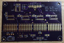
I have been quietly designing and making PCB's to try a 16-bit sine weighted average differential circuit with my Amanero. I should have all the parts by Monday and be able to get a first listen by the middle of next week. I also bought a solder paste stencil and reflow oven to make things easier. See attached pictures.
The largest changes from the Chinese DSC1 differential design are:
1. Muting is done with analog switches to a 2.5V reference. An NE555 circuit provides an adjustable time delay before re-enabling the outputs. Also, the 74AHCT595 bit shift IC's are put into High-Z mode during muting.
2. Two 2012 SMD resistors in series provide a 0.1% accurate sine weighted profile.
3. The bit shift and buffer output clock signals are delayed to make sure that they arrive at the bit shift IC's after the DSD data bits arrive.
4. I use one board for Amanero interface, muting, and clock delay and two stacked boards for the 16-Bit Sine weighting of differential signals to my Cinemag output transformers.
I continue to employ the brilliant idea of using an XOR chip to create the DSD+ and DSD- bit streams. I bought Potato Semi IC's for this. No tiny chips here.
The Japanese resistor profile appears to resemble a normal distribution curve or an exponential decay. If Sine wave weighting doesn't sound right I can always try a different profile.
The thread has gone a bit quiet.
I have been quietly designing and making PCB's to try a 16-bit sine weighted average differential circuit with my Amanero. I should have all the parts by Monday and be able to get a first listen by the middle of next week. I also bought a solder paste stencil and reflow oven to make things easier. See attached pictures.
The largest changes from the Chinese DSC1 differential design are:
1. Muting is done with analog switches to a 2.5V reference. An NE555 circuit provides an adjustable time delay before re-enabling the outputs. Also, the 74AHCT595 bit shift IC's are put into High-Z mode during muting.
2. Two 2012 SMD resistors in series provide a 0.1% accurate sine weighted profile.
3. The bit shift and buffer output clock signals are delayed to make sure that they arrive at the bit shift IC's after the DSD data bits arrive.
4. I use one board for Amanero interface, muting, and clock delay and two stacked boards for the 16-Bit Sine weighting of differential signals to my Cinemag output transformers.
I continue to employ the brilliant idea of using an XOR chip to create the DSD+ and DSD- bit streams. I bought Potato Semi IC's for this. No tiny chips here.
The Japanese resistor profile appears to resemble a normal distribution curve or an exponential decay. If Sine wave weighting doesn't sound right I can always try a different profile.
Attachments
Thanks for the update carlsor, I await further progress with interest and I'll probably hold off ordering any boards until I hear about your results. Good luck.
Can you share a part number or Mouser link? I don't want to use those really tiny parts either!
The Japanese schematic is using flip-flops instead of shift registers - any thoughts?
I've also been thinking about making the resistor networks as plug-in modules to make trying different filters easier.
Ray
I continue to employ the brilliant idea of using an XOR chip to create the DSD+ and DSD- bit streams. I bought Potato Semi IC's for this. No tiny chips here.
Can you share a part number or Mouser link? I don't want to use those really tiny parts either!
The Japanese schematic is using flip-flops instead of shift registers - any thoughts?
I've also been thinking about making the resistor networks as plug-in modules to make trying different filters easier.
Ray
Here is the link to Potato Semicconduction Co.
7486 G Series GHz TTL CMOS logic IC 14pin SOIC QTY-1 | eBay
The cost is $3usd each plus shipping. This is the fastest and lowest noise chip of its kind.
Where can you get 10 boards for $25? I can't even get blank boards for twice that price.
I don't see any flip-flops in the Japanese circuit. Also, I don't see any circuit or component selection ideas that would change what I have done so far.
Here is the link to Potato Semicconduction Co.
7486 G Series GHz TTL CMOS logic IC 14pin SOIC QTY-1 | eBay
The cost is $3usd each plus shipping. This is the fastest and lowest noise chip of its kind.
Where can you get 10 boards for $25? I can't even get blank boards for twice that price.
I don't see any flip-flops in the Japanese circuit. Also, I don't see any circuit or component selection ideas that would change what I have done so far.
Thanks Carlsor.
These are the devices used for the filters in the Japanese circuit;
http://www.mouser.co.uk/Search/Prod...virtualkey59500000virtualkey595-SN74AHC574NSR
I get my PCBs fabricated here, very cheap if you can work within their board size constraints, pretty good quality too.
Dirt Cheap Dirty Boards
Ray
Hello Carlsor.
Very interesting project.
Could you please post a schematic of the Interface/Mute circuit?
I am sure that a lot of us could use your solution to those pesky switching clicks and pops.
Nic.
Very interesting project.
Could you please post a schematic of the Interface/Mute circuit?
I am sure that a lot of us could use your solution to those pesky switching clicks and pops.
Nic.
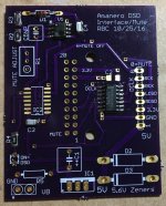
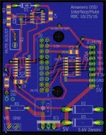
Amanero Interface/Mute circuit
The 5.6V Zeners are optional. They protect all 5V components from a catastrophic failure in my DIY 5V Vreg.
See schematic and PCB pictures below. This unit works, however a bad batch of 74ahct595 chips has kept me from having a completely functioning 16-bit DSD unit at this time.Could you please post a schematic of the Interface/Mute circuit?
The 5.6V Zeners are optional. They protect all 5V components from a catastrophic failure in my DIY 5V Vreg.
Attachments
Carlsor
Thank you very much for the schematics of your project.
I have been trying to match it with the solder mask of the dac end from your post 391 above to see how the XOR chip from Potato Semi is hooked up. My aging eyes and brains are not up to the task!
So, could you please post the circuit diagram for the 16bit pcb ?
Is the chip designated as U3 on the board the PO74G86A? The reason I ask is this seems to be a 4 input chip...
Thanks in advance.
Nic
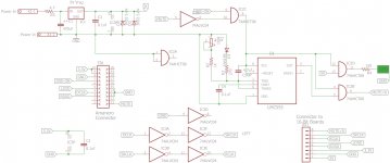
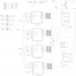
16bit pcb schematic
See attached Schematic for existing PCB. The next version will need a TS5A3167 NC analog switch to put the outputs to Mute when there is no 3.3V power coming from the Amanero. After testing there may be other changes.
Yes, V3 is a PO74G86A which is low noise and fast enough to get signals to the bit shift ICs ahead of the clock signals. It is the larger SOIC package which is easier to solder, but only comes with 4 XOR gates. I use the 3rd gate to invert the MUTE signal which closes the TS5A3166 NO analog switches to 2.5V reference and puts the 74AHCT595 chips in high-Z output mode.
I have 40 more 74AHCT595 chips arriving this Thursday from a different manufacturer. I keep destroying the ones from TI with heat. I had no problem hand soldering the 16 TI 74AHCT595 chips that came with the Chinese Diff DSC1 kit, but the bunch I got from Mouser seem much more heat sensitive.
I didn't want to spend too much time getting into the details of this circuit until I had a great sounding prototype.
could you please post the circuit diagram for the 16bit pcb ?
See attached Schematic for existing PCB. The next version will need a TS5A3167 NC analog switch to put the outputs to Mute when there is no 3.3V power coming from the Amanero. After testing there may be other changes.
Yes, V3 is a PO74G86A which is low noise and fast enough to get signals to the bit shift ICs ahead of the clock signals. It is the larger SOIC package which is easier to solder, but only comes with 4 XOR gates. I use the 3rd gate to invert the MUTE signal which closes the TS5A3166 NO analog switches to 2.5V reference and puts the 74AHCT595 chips in high-Z output mode.
I have 40 more 74AHCT595 chips arriving this Thursday from a different manufacturer. I keep destroying the ones from TI with heat. I had no problem hand soldering the 16 TI 74AHCT595 chips that came with the Chinese Diff DSC1 kit, but the bunch I got from Mouser seem much more heat sensitive.
I didn't want to spend too much time getting into the details of this circuit until I had a great sounding prototype.
Attachments
74AHCT595 Chips Still Failing
I received a bunch of 74AHCT595 chips made by Diodes Inc. instead of by TI. Same problem. I am doing only careful hand soldering and have had more fail than survive. One that survived the soldering had a channel fail later. It has been a long time since I destroyed even one IC chip. In most cases, the ones that didn't fail completely have more channel to channel variation then I would like.
The outputs of these chips are the beginning of the analog signal, so the channels should ideally function at the same voltage output into the same resistance to minimize distortion. Low and high output channels should be mirror images of rise/fall time and voltage.
The best sound I achieved earlier in a SE design was with 74VHC595 chips feeding 74ALC244 buffer chips and then to the resistors. There was a residual hardness to the sound that I couldn't figure out, but may have originated in the JLSounds USB->DSD card which I had partially fried. The music was incredible in some ways.
This project is taking much more time than I expected. I need to step away from it to do other things and rethink this project. Any suggestions are welcome.
Carlsor,
This is really a bad piece of news...
unfortunately I haven't competence enough to suggest somenthing intelligent.
For sure SN74AHCT595 from TI, available also in PDIP package, appears more realiable.
But I don't know if operating frequency (max 110 MHz) or other features are appropriate
This is really a bad piece of news...
unfortunately I haven't competence enough to suggest somenthing intelligent.
For sure SN74AHCT595 from TI, available also in PDIP package, appears more realiable.
But I don't know if operating frequency (max 110 MHz) or other features are appropriate
- Home
- Source & Line
- Digital Line Level
- Signalyst DSC1