Carlsor, I'm very sorry about Your hearing problem. I hope that You can re-gain good function quickly.
I admit to not understand how this "moving average filter" works, so I will try to acquire something from Terry's explanation...
So, if I'm correct, the 595s should work on a constant load. Then a I/V converter should transduce the musical information into Voltage
I admit to not understand how this "moving average filter" works, so I will try to acquire something from Terry's explanation...
So, if I'm correct, the 595s should work on a constant load. Then a I/V converter should transduce the musical information into Voltage
Is there a specific goal regarding "16 bit" sine weighted filter as opposed to 31 bit equal weighted filter? Sees like reducing bits by 1/2 and then weighting gives a substantial reduction in the effectiveness of the filter, as well as being more complicated?
Sent from my iPhone using Tapatalk
Sent from my iPhone using Tapatalk
Since the filter works just like a FIR filter, but in analog domain, the tap (resistor) values define impulse response and thus frequency response of the conversion stage. You can easily calculate frequency response from the resistor values.
I had my reasons for using equally weighted conversion stage (like most delta-sigma DAC chips do too).
Variations in the resistor values don't cause distortion or change the waveform directly, they just alter the transfer function - frequency response of the conversion stage.
Equally weighted stage gives comb-filter frequency response, linear step response and minimizes jitter sensitivity.
I have been asked what I did to eliminate the noise problem that some are hearing. With earlier versions, I heard noise/hiss whenever there was a bad solder joint of a resistor or a blown/weak channel coming from a "595" bit shift chip. I suggest than if a DSC1 has hiss - that every bit shift output channel be checked with a volt meter. There should be a music signal going through the DSC1 during the test. The outputs of my latest 74VHC595 build ranged from 2.481-2.485 volts.
Each DSD bit sweeps through the 16 bit positions having very little influence on the combined output at the start and then ramping up until it gets to bits 8 and 9 where it has the greatest effect on the output voltage and then tapers back off. I picked an even number of bits with the middle two bits having equal resistor values instead of an odd number of bits with a single lowest value resistor in the middle to process a 0 analog voltage properly. In DSD, 0 analog volts is represented by a 101010101010101..... signal. This would result in noise with an odd number of sine bits but cancels perfectly with an even number of bits. This is not an issue with all output resistors having the same value.
The goal of a 16 bit sine weighted filter was to preserve more musical detail that was missing to my ears from the 32 bit equal weighted Chinese differential filter. Too much filtering erases some of the musical content.
Still a few more days for the break-in period to complete with the music going back and forth between rough patches and glorious sound. My ears have cleared up a bit and I really like the best of what I am hearing.
What will be the result of a 8-bit, equal resistor filter (like the output of a ES9018 chip) ? Like here: audiodesignguide.com/DAC32/index.html
Does the sinewave mapped through the resistor values makes the "random digital" noise a sinewave-shaped noise?
Does the sinewave mapped through the resistor values makes the "random digital" noise a sinewave-shaped noise?
The goal of a 16 bit sine weighted filter was to preserve more musical detail that was missing to my ears from the 32 bit equal weighted Chinese differential filter. Too much filtering erases some of the musical content.
.
For single rate DSD64 the clock rate is 2.8 MHz which div 31 = 90kHz so I presume it should not filter out important parts of your music ... now for DSD512 one could argue that >31 bits would be ideal but there is a law of diminishing returns
No-DAC DSD project update
All my listening was done at a DSD rate of 2xDSD DoP. This would translate to a frequency of 360KHz with a 16-bit filter.
I never heard any noise. Sine-wave weighted noise would still sound like noise.
I did careful listening today with my Grado GS1000 headphones. My ears have cleared up a bit. The bass is the deepest and punchiest I have ever heard with these headphones. Lots of detail and musical energy. Still a bit of new parts sound. I'm sure younger ears can do a better job of evaluating this NO-DAC DSD design - which sounds far better to me than any of my earlier DSD project attempts.
I would like to hand this project to someone else to improve on because my life has become swamped with other priorities. Perhaps it can be improved with the AD844 IV, on-board individual Vregs, 24-Bits, a second stage with a more powerful buffer such as the "244" IC, different resistors values, pluggable/changeable resister arrays, optimum load capacitor/resistor/Zobel filter, reclocker, etc. Maybe it is good enough like it is using all premium power supplies and components.
I have 2 Amanero interface-mute PCB's, one 16-bit digital averaging PCB with solder paste stencil, and will be receiving 3 buffer PCBs soon. Any interest? I will give my Eagle PCB files to anyone who is interested.
Ok so if you are using DSD128, the math doesn't support the 31 bit FIR as having any negative impact on sound, nor do I see any rationale for sine weighted resistors.
Sent from my iPhone using Tapatalk
Sent from my iPhone using Tapatalk
Thank You Carlsor, I got all the files 🙂. Happy Christmas to You and S.I will give my Eagle PCB files to anyone who is interested.
 !
!What will be the result of a 8-bit, equal resistor filter (like the output of a ES9018 chip) ?
ESS Sabre has 64 equal weighted conversion elements per channel. If you gang all channels of 8-channel chip together you get total 512 equal weighted elements, grouped as 8x64 parallel set.
For comparison dCS DACs have 24 equal weighted elements per differential side, so 48 total per channel.
Does the sinewave mapped through the resistor values makes the "random digital" noise a sinewave-shaped noise?
No, the weighting changes just frequency response of the filter. Preferred values also depend on what sample rates are to be optimized. I chose to optimize for DSD256/DSD512 because I play all DSD64/DSD128 upsampled to those rates, so my DSC1 is never used at DSD64.
For playing DSD64 straight, that sine weighted is probably better one, it trades some jitter insensitivity for frequency response. At DSD64 rate it begins to cut at 100 kHz. For DSD64 it is also better to move the analog filter down to 50 kHz instead of the original 100 kHz.
ESS Sabre has 64 equal weighted conversion elements per channel. If you gang all channels of 8-channel chip together you get total 512 equal weighted elements, grouped as 8x64 parallel set.
For comparison dCS DACs have 24 equal weighted elements per differential side, so 48 total per channel.
Sorry, I was not clear enough. I do not intend to put in parallel eight ES9018 chips.
I want to consider a 8-bit (equally weighted = eight same value resistors) filter instead of a 16-bit filter. Hence use only two 595s (one 595 chip for DSD+ and one 595 chip for DSD-) instead of four.
No, the weighting changes just frequency response of the filter. Preferred values also depend on what sample rates are to be optimized. I chose to optimize for DSD256/DSD512 because I play all DSD64/DSD128 upsampled to those rates, so my DSC1 is never used at DSD64.
What resistor value to choose (playing DSD256)? Which is the relation between resistor value and cutoff frequency? Does it depend also from the output capacitor value (connected to ground) like a RC filter?
I plan to use the printed circuit board design by Signalyst.
If someone has the printed circuit board in Gerber format or another format for producing one, i would be grateful.
I am going to build one by pcbshopper.
If you are interested in a printed circuit board, tell me.
Thank you
If someone has the printed circuit board in Gerber format or another format for producing one, i would be grateful.
I am going to build one by pcbshopper.
If you are interested in a printed circuit board, tell me.
Thank you
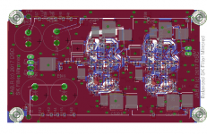
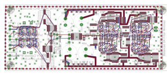
Balanced DSC Discrete SK filters
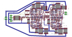
I've previously posted the Balanced digital section of the DSCx DAC with the clock optimized board. For the analog section there is an advantage to mirror. Here is a mirrored SK filter section using Wurcer's discrete JFET op amp cascoded with BJT devices. The low noise BF862 jFet is used. The advantage is that these devices are current production, inexpensive and low noise.
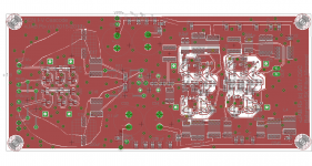
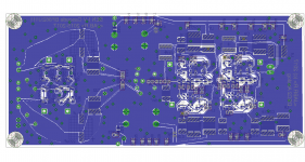
A two layered SMD board is used with +/- on either side of the board.
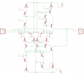
View attachment Wurcer Disc OPA.pdf
View attachment SK mirror.pdf
I've previously posted the Balanced digital section of the DSCx DAC with the clock optimized board. For the analog section there is an advantage to mirror. Here is a mirrored SK filter section using Wurcer's discrete JFET op amp cascoded with BJT devices. The low noise BF862 jFet is used. The advantage is that these devices are current production, inexpensive and low noise.
A two layered SMD board is used with +/- on either side of the board.


View attachment Wurcer Disc OPA.pdf
View attachment SK mirror.pdf
Last edited:
Not the final board but this is a Balanced, Discrete, Mirrored analog section. Probably can take out the coupling capacitor between the I-V section on the left and the SK filter on the right.
View attachment 593990
This looks very interesting! Any plans to build it?
This looks very interesting! Any plans to build it?
Still finalizing the layout, but certainly.
Still finalizing the layout, but certainly.
Very neat! Looking forward to see how it works out, and definitely interested in trying them out.
Last edited:
- Home
- Source & Line
- Digital Line Level
- Signalyst DSC1
